Shader semantics
When writing HLSL shader programs, input and output variables need to have their “intent” indicated via semantics. This is a standard concept in HLSL shader language; see the Semantics documentation on MSDN for more details.
You can download the examples shown below as a zipped Unity project, here.
Vertex shader input semantics
The main vertex shader function (indicated by the #pragma vertex
directive) needs to have semantics on all of the input parameters.
These correspond to individual Mesh data elements, like vertex position, normal mesh, and texture coordinates.
See vertex program inputs for more details.
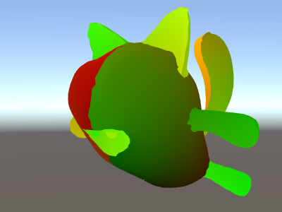
Here’s an example of a simple vertex shader that takes vertex position and a texture coordinate as an input. The pixel shader visualizes the texture coordinate as a color.
Shader "Unlit/Show UVs"
{
    SubShader
    {
        Pass
        {
            CGPROGRAM
            #pragma vertex vert
            #pragma fragment frag

            struct v2f {
                float2 uv : TEXCOORD0;
                float4 pos : SV_POSITION;
            };

            v2f vert (
                float4 vertex : POSITION, // vertex position input
                float2 uv : TEXCOORD0 // first texture coordinate input
                )
            {
                v2f o;
                o.pos = UnityObjectToClipPos(vertex);
                o.uv = uv;
                return o;
            }

            fixed4 frag (v2f i) : SV_Target
            {
                return fixed4(i.uv, 0, 0);
            }
            ENDCG
        }
    }
}
Instead of spelling out all individual inputs one by one, it is also possible to declare a structure of them, and indicate semantics on each individual member variable of the struct. See shader program examples to learn how to do this.
Fragment shader output semantics
Most often a fragment (pixel) shader outputs a color, and has an
SV_Target semantic. The fragment shader in the example above does
exactly that:
fixed4 frag (v2f i) : SV_Target
The function frag has a return type of fixed4 (low precision
RGBA color). As it only returns a single value, the semantic
is indicated on the function itself, : SV_Target.
It is also possible to return a structure with the outputs. The fragment shader above could be rewritten this way too, and it would do exactly the same:
struct fragOutput {
    fixed4 color : SV_Target;
};
fragOutput frag (v2f i)
{
    fragOutput o;
    o.color = fixed4(i.uv, 0, 0);
    return o;
}
Returning structures from the fragment shader is mostly useful for shaders that don’t just return a single color. Additional semantics supported by the fragment shader outputs are as follows.
SV_TargetN: Multiple render targets
SV_Target1, SV_Target2, etc.: These are additional colors written by the shader. This is used when rendering into more than one render target at once (known as the Multiple Render Targets rendering technique, or MRT). SV_Target0 is the same as SV_Target.
SV_Depth: Pixel shader depth output
Usually the fragment shader does not override the Z buffer value, and a default value is used from the regular triangle rasterization. However, for some effects it is useful to output custom Z buffer depth values per pixel.
Note that on many GPUs this turns off some depth buffer optimizations, so do not override Z buffer value without a good reason. The cost incurred by SV_Depth varies depending on the GPU architecture, but overall it’s fairly similar to the cost of alpha testing (using the built-in clip() function in HLSL). Render shaders that modify depth after all regular opaque shaders (for example, by using the AlphaTest rendering queue.
The depth output value needs to be a single float.
Vertex shader outputs and fragment shader inputs
A vertex shader needs to output the final clip space position of a vertex, so that the GPU knows where on the screen to rasterize it, and at what depth. This output needs to have the SV_POSITION semantic, and be of a float4 type.
Any other outputs (“interpolators” or “varyings”) produced by the vertex shader are whatever your particular shader needs. The values output from the vertex shader will be interpolated across the face of the rendered triangles, and the values at each pixel will be passed as inputs to the fragment shader.
Many modern GPUs don’t really care what semantics these variables have; however some old systems (most notably, shader model 2 GPUs on Direct3D 9) did have special rules about the semantics:
-
TEXCOORD0,TEXCOORD1etc are used to indicate arbitrary high precision data such as texture coordinates and positions. -
COLOR0andCOLOR1semantics on vertex outputs and fragment inputs are for low-precision, 0–1 range data (like simple color values).
For best cross platform support, label vertex outputs and
fragment inputs as TEXCOORDn semantics.
See shader program examples for examples.
Interpolator count limits
There are limits to how many interpolator variables can be used in total to pass the information from the vertex into the fragment shader. The limit depends on the platform and GPU, and the general guidelines are:
-
Up to 8 interpolators: OpenGL ES 2.0 (iOS/Android), Direct3D 11 9.x level
(Windows Phone) and Direct3 9 shader model 2.0 (old PCs). Since the interpolator
count is limited, but each interpolator can be a 4-component vector,
some shaders pack things together to stay within limits. For example, two texture
coordinates can be passed in one
float4variable (.xy for one coordinate, .zw for the second coordinate). -
Up to 10 interpolators: Direct3D 9 shader model 3.0 (
#pragma target 3.0). - Up to 16 interpolators: OpenGL ES 3.0 (iOS/Android), Metal (iOS).
-
Up to 32 interpolators: Direct3D 10 shader model 4.0 (
#pragma target 4.0).
Regardless of your particular target hardware, it is generally a good idea to use as few interpolators as possible for performance reasons.
Other special semantics
Screen space pixel position: VPOS
A fragment shader can receive position of the pixel being rendered as a special VPOS semantic.
This feature only exists starting with shader model 3.0, so the shader needs to have the #pragma target 3.0 compilation directive.
On different platforms the underlying type of the screen space position input varies, so for maximum portability use the UNITY_VPOS_TYPE type for it (it will be float4 on most platforms, and float2 on Direct3D 9).
Additionally, using the pixel position semantic makes it hard to have both the clip space position (SV_POSITION) and VPOS in the same vertex-to-fragment structure. So the vertex shader should output the clip space position as a separate “out” variable. See the example shader below:
Shader "Unlit/Screen Position"
{
Properties
{
_MainTex ("Texture", 2D) = "white" {}
}
SubShader
{
Pass
{
CGPROGRAM
#pragma vertex vert
#pragma fragment frag
#pragma target 3.0
// note: no SV_POSITION in this struct
struct v2f {
float2 uv : TEXCOORD0;
};
v2f vert (
float4 vertex : POSITION, // vertex position input
float2 uv : TEXCOORD0, // texture coordinate input
out float4 outpos : SV_POSITION // clip space position output
)
{
v2f o;
o.uv = uv;
outpos = UnityObjectToClipPos(vertex);
return o;
}
sampler2D _MainTex;
fixed4 frag (v2f i, UNITY_VPOS_TYPE screenPos : VPOS) : SV_Target
{
// screenPos.xy will contain pixel integer coordinates.
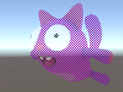
// use them to implement a checkerboard pattern that skips rendering
// 4x4 blocks of pixels
// checker value will be negative for 4x4 blocks of pixels
// in a checkerboard pattern
screenPos.xy = floor(screenPos.xy * 0.25) * 0.5;
float checker = -frac(screenPos.r + screenPos.g);
// clip HLSL instruction stops rendering a pixel if value is negative
clip(checker);
// for pixels that were kept, read the texture and output it
fixed4 c = tex2D (_MainTex, i.uv);
return c;
}
ENDCG
}
}
}
Face orientation: VFACE
A fragment shader can receive a variable that indicates whether the rendered surface is facing the camera, or facing away from the camera. This is useful when rendering geometry that should be visible from both sides – often used on leaves and similar thin objects. The VFACE semantic input variable will contain a positive value for front-facing triangles, and a negative value for back-facing ones.
This feature only exists from shader model 3.0 onwards, so the shader needs to have the #pragma target 3.0 compilation directive.
Shader "Unlit/Face Orientation"
{
    Properties
    {
        _ColorFront ("Front Color", Color) = (1,0.7,0.7,1)
        _ColorBack ("Back Color", Color) = (0.7,1,0.7,1)
    }
    SubShader
    {
        Pass
        {
            Cull Off // turn off backface culling

            CGPROGRAM
            #pragma vertex vert
            #pragma fragment frag
            #pragma target 3.0

            float4 vert (float4 vertex : POSITION) : SV_POSITION
            {
                return UnityObjectToClipPos(vertex);
            }

            fixed4 _ColorFront;
            fixed4 _ColorBack;

            fixed4 frag (fixed facing : VFACE) : SV_Target
            {
                // VFACE input positive for frontbaces,
                // negative for backfaces. Output one
                // of the two colors depending on that.
                return facing > 0 ? _ColorFront : _ColorBack;
            }
            ENDCG
        }
    }
}
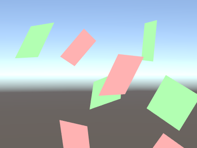
The shader above uses the Cull state to turn off backface culling (by default back-facing triangles are not rendered at all). Here is the shader applied to a bunch of Quad meshes, rotated at different orientations:
Vertex ID: SV_VertexID
A vertex shader can receive a variable that has the “vertex number” as an unsigned integer. This is mostly useful when you want to fetch additional per-vertex data from textures or ComputeBuffers.
This feature only exists from DX10 (shader model 4.0) and GLCore / OpenGL ES 3, so the shader needs to have the #pragma target 3.5 compilation directive.
Shader "Unlit/VertexID"
{
SubShader
{
Pass
{
CGPROGRAM
#pragma vertex vert
#pragma fragment frag
#pragma target 3.5
struct v2f {
fixed4 color : TEXCOORD0;
float4 pos : SV_POSITION;
};
v2f vert (
float4 vertex : POSITION, // vertex position input
uint vid : SV_VertexID // vertex ID, needs to be uint
)
{
v2f o;
o.pos = UnityObjectToClipPos(vertex);
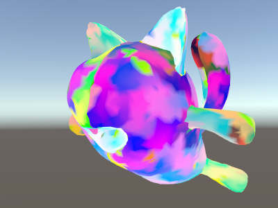
// output funky colors based on vertex ID
float f = (float)vid;
o.color = half4(sin(f/10),sin(f/100),sin(f/1000),0) * 0.5 + 0.5;
return o;
}
fixed4 frag (v2f i) : SV_Target
{
return i.color;
}
ENDCG
}
}
}
(You can download the examples shown above as a zipped Unity project, here)
对文档有任何疑问,请移步至开发者社区提问,我们将尽快为您解答