Providing vertex data to vertex programs
For Cg/HLSL vertex programs, the
MeshThe main graphics primitive of Unity. Meshes make up a large part of your 3D worlds. Unity supports triangulated or Quadrangulated polygon meshes. Nurbs, Nurms, Subdiv surfaces must be converted to polygons. More info
See in Glossary vertex data is passed as inputs to the vertex
shader function. Each input needs to have semantic speficied for it: for example, POSITION input is the vertex position, and NORMAL is the vertex normal.
Often, vertex data inputs are declared in a structure, instead of listing them one by one. Several commonly used vertex structures are defined in UnityCG.cginc include file, and in most cases it’s enough just to use those. The structures are:
-
appdata_base: position, normal and one texture coordinate. -
appdata_tan: position, tangent, normal and one texture coordinate. -
appdata_full: position, tangent, normal, four texture coordinates and color.
Example: This shaderA small script that contains the mathematical calculations and algorithms for calculating the Color of each pixel rendered, based on the lighting input and the Material configuration. More info
See in Glossary colors the mesh based on its normals, and uses appdata_base as vertex program input:
Shader "VertexInputSimple" {
    SubShader {
        Pass {
            CGPROGRAM
            #pragma vertex vert
            #pragma fragment frag
            #include "UnityCG.cginc"

            struct v2f {
                float4 pos : SV_POSITION;
                fixed4 color : COLOR;
            };

            v2f vert (appdata_base v)
            {
                v2f o;
                o.pos = UnityObjectToClipPos(v.vertex);
                o.color.xyz = v.normal * 0.5 + 0.5;
                o.color.w = 1.0;
                return o;
            }

            fixed4 frag (v2f i) : SV_Target { return i.color; }
            ENDCG
        }
    }
}
To access different vertex data, you need to declare the vertex structure yourself, or add input parameters to the vertex shader. Vertex data is identified by Cg/HLSL semantics, and must be from the following list:
-
POSITIONis the vertex position, typically afloat3orfloat4. -
NORMALis the vertex normal, typically afloat3. -
TEXCOORD0is the first UV coordinate, typicallyfloat2,float3orfloat4. -
TEXCOORD1,TEXCOORD2andTEXCOORD3are the 2nd, 3rd and 4th UV coordinates, respectively. -
TANGENTis the tangent vector (used for normal mapping), typically afloat4. -
COLORis the per-vertex color, typically afloat4.
When the mesh data contains fewer components than are needed by the vertex
shader input, the rest are filled with zeroes, except for the .w
component which defaults to 1. For example, mesh texture coordinates
are often 2D vectors with just x and y components. If a vertex
shader declares a float4 input with TEXCOORD0 semantic, the
value received by the vertex shaderA program that runs on each vertex of a 3D model when the model is being rendered. More info
See in Glossary will contain (x,y,0,1).
Examples
Visualizing UVs
The following shader example uses the vertex position and the first texture coordinate as the vertex shader inputs (defined in the structure appdata). This shader is very useful for debugging the UV coordinates of the mesh.
Shader "Debug/UV 1" {
SubShader {
    Pass {
        CGPROGRAM
        #pragma vertex vert
        #pragma fragment frag
        #include "UnityCG.cginc"

        // vertex input: position, UV
        struct appdata {
            float4 vertex : POSITION;
            float4 texcoord : TEXCOORD0;
        };

        struct v2f {
            float4 pos : SV_POSITION;
            float4 uv : TEXCOORD0;
        };

        v2f vert (appdata v) {
            v2f o;
            o.pos = UnityObjectToClipPos(v.vertex );
            o.uv = float4( v.texcoord.xy, 0, 0 );
            return o;
        }

        half4 frag( v2f i ) : SV_Target {
            half4 c = frac( i.uv );
            if (any(saturate(i.uv) - i.uv))
                c.b = 0.5;
            return c;
        }
        ENDCG
    }
}
}
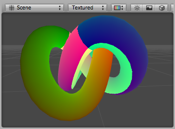
Here, UV coordinates are visualized as red and green colors, while an additional blue tint has been applied to coordinates outside of the 0 to 1 range:

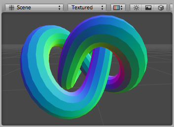
Similarly, this shader vizualizes the second UV set of the model:
Shader "Debug/UV 2" {
SubShader {
    Pass {
        CGPROGRAM
        #pragma vertex vert
        #pragma fragment frag
        #include "UnityCG.cginc"

        // vertex input: position, second UV
        struct appdata {
            float4 vertex : POSITION;
            float4 texcoord1 : TEXCOORD1;
        };

        struct v2f {
            float4 pos : SV_POSITION;
            float4 uv : TEXCOORD0;
        };

        v2f vert (appdata v) {
            v2f o;
            o.pos = UnityObjectToClipPos(v.vertex );
            o.uv = float4( v.texcoord1.xy, 0, 0 );
            return o;
        }

        half4 frag( v2f i ) : SV_Target {
            half4 c = frac( i.uv );
            if (any(saturate(i.uv) - i.uv))
                c.b = 0.5;
            return c;
        }
        ENDCG
    }
}
}
Visualizing vertex colors
The following shader uses the vertex position and the per-vertex colors as the vertex shader inputs (defined in structure appdata).
Shader "Debug/Vertex color" {
SubShader {
    Pass {
        CGPROGRAM
        #pragma vertex vert
        #pragma fragment frag
        #include "UnityCG.cginc"

        // vertex input: position, color
        struct appdata {
            float4 vertex : POSITION;
            fixed4 color : COLOR;
        };

        struct v2f {
            float4 pos : SV_POSITION;
            fixed4 color : COLOR;
        };

        v2f vert (appdata v) {
            v2f o;
            o.pos = UnityObjectToClipPos(v.vertex );
            o.color = v.color;
            return o;
        }

        fixed4 frag (v2f i) : SV_Target { return i.color; }
        ENDCG
    }
}
}

Visualizing normals
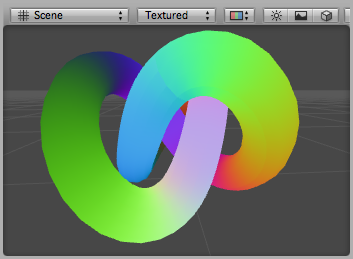
The following shader uses the vertex position and the normal as the vertex shader inputs (defined in the structure appdata). The normal’s X,Y & Z components are visualized as RGB colors. Because the normal components are in the –1 to 1 range, we scale and bias them so that the output colors are displayable in the 0 to 1 range.
Shader "Debug/Normals" {
SubShader {
    Pass {
        CGPROGRAM
        #pragma vertex vert
        #pragma fragment frag
        #include "UnityCG.cginc"

        // vertex input: position, normal
        struct appdata {
            float4 vertex : POSITION;
            float3 normal : NORMAL;
        };

        struct v2f {
            float4 pos : SV_POSITION;
            fixed4 color : COLOR;
        };

        v2f vert (appdata v) {
            v2f o;
            o.pos = UnityObjectToClipPos(v.vertex );
            o.color.xyz = v.normal * 0.5 + 0.5;
            o.color.w = 1.0;
            return o;
        }

        fixed4 frag (v2f i) : SV_Target { return i.color; }
        ENDCG
    }
}
}

Visualizing tangents and binormals
Tangent and binormal vectors are used for normal mapping. In Unity only the tangent vector is stored in vertices, and the binormal is derived from the normal and tangent values.
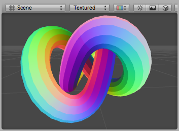
The following shader uses the vertex position and the tangent as vertex shader inputs (defined in structure appdata). Tangent’s x,y and z components are visualized as RGB colors. Because the normal components are in the –1 to 1 range, we scale and bias them so that the output colors are in a displayable 0 to 1 range.
Shader "Debug/Tangents" {
SubShader {
    Pass {
        CGPROGRAM
        #pragma vertex vert
        #pragma fragment frag
        #include "UnityCG.cginc"

        // vertex input: position, tangent
        struct appdata {
            float4 vertex : POSITION;
            float4 tangent : TANGENT;
        };

        struct v2f {
            float4 pos : SV_POSITION;
            fixed4 color : COLOR;
        };

        v2f vert (appdata v) {
            v2f o;
            o.pos = UnityObjectToClipPos(v.vertex );
            o.color = v.tangent * 0.5 + 0.5;
            return o;
        }

        fixed4 frag (v2f i) : SV_Target { return i.color; }
        ENDCG
    }
}
}

The following shader visualizes bitangents. It uses the vertex position, normal and tangent values as vertex inputs. The bitangent (sometimes called binormal) is calculated from the normal and tangent values. It needs to be scaled and biased into a displayable 0 to 1 range.
Shader "Debug/Bitangents" {
SubShader {
    Pass {
        Fog { Mode Off }
        CGPROGRAM
        #pragma vertex vert
        #pragma fragment frag
        #include "UnityCG.cginc"

        // vertex input: position, normal, tangent
        struct appdata {
            float4 vertex : POSITION;
            float3 normal : NORMAL;
            float4 tangent : TANGENT;
        };

        struct v2f {
            float4 pos : SV_POSITION;
            float4 color : COLOR;
        };

        v2f vert (appdata v) {
            v2f o;
            o.pos = UnityObjectToClipPos(v.vertex );
            // calculate bitangent
            float3 bitangent = cross( v.normal, v.tangent.xyz ) * v.tangent.w;
            o.color.xyz = bitangent * 0.5 + 0.5;
            o.color.w = 1.0;
            return o;
        }

        fixed4 frag (v2f i) : SV_Target { return i.color; }
        ENDCG
    }
}
}
