2D Blending
The first option in the InspectorA Unity window that displays information about the currently selected GameObject, asset or project settings, allowing you to inspect and edit the values. More info
See in Glossary of a Blend NodeA node in a Blend Tree graph that blends animation clip nodes. More info
See in Glossary is the Blend Type. This drop-down is used to select one of the different blend types that can blend according to one or two parameters. The 2D blending types blends the child motions according to two parameters.
The different 2D Blend Types have different uses that they are suitable for. They differ in how the influence of each motion is calculated.
2D Simple Directional: Best used when your motions represent different directions, such as “walk forward”, “walk backward”, “walk left”, and “walk right”, or “aim up”, “aim down”, “aim left”, and “aim right”. Optionally a single motion at position (0, 0) can be included, such as “idle” or “aim straight”. In the Simple Directional type there should not be multiple motions in the same direction, such as “walk forward” and “run forward”.
2D Freeform Directional: This blend type is also used when your motions represent different directions, however you can have multiple motions in the same direction, for example “walk forward” and “run forward”. In the Freeform Directional type the set of motions should always include a single motion at position (0, 0), such as “idle”.
2D Freeform Cartesian: Best used when your motions do not represent different directions. With Freeform Cartesian your X parameter and Y parameter can represent different concepts, such as angular speed and linear speed. An example would be motions such as “walk forward no turn”, “run forward no turn”, “walk forward turn right”, “run forward turn right” etc.
Direct: This type of blend tree lets user control the weight of each node directly. Useful for facial shapes or random idle blending.
After setting the Blend Type, the first thing you need is to select the two Animation ParametersUsed to communicate between scripting and the Animator Controller. Some parameters can be set in scripting and used by the controller, while other parameters are based on Custom Curves in Animation Clips and can be sampled using the scripting API. More info
See in Glossary that will control this Blend Tree. In this example, the parameters are velocityX (strafing) and velocityZ (forward speed).
Then you can add individual animations by clicking + -> Add Motion Field to add an Animation Clip to the blend tree. When you’re done, it should look something like this:
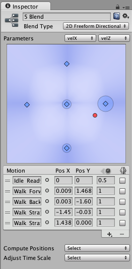
The positions in 2D blending are like the thresholds in 1D blending, except that there are two values instead of one, corresponding to each of the two parameters. Their positions along the horizontal X axis correspond to the first parameter, and their positions along the vertical Y axis correspond to the second parameter. A walking forward animation might have a velocityX of 0 and a velocityZ of 1.5, so those values should be typed into the Pos X and Pos Y number fields for the motion.
The 2D Blending Diagram
The diagram at the top of the Inspector shows the positions of the child motions in the 2D blend space. The motions are shown as blue dots. Motions with no Animation ClipAnimation data that can be used for animated characters or simple animations. It is a simple “unit” piece of motion, such as (one specific instance of) “Idle”, “Walk” or “Run”. More info
See in Glossary or Blend Tree assigned have no influence on the blend and are shown as gray dots. You can select a motion by clicking on its dot in the diagram. Once selected, the influence of that motion for each point in the blending space is visualized as a blue field. The field is strongest right under the position of the motion, where the motion has full influence, meaning that its animation weight is 1 and the other animations have a weight of 0. Further away the influence decreases as the influence of other motions take over.

The red dot indicates the values of the two Parameters. If you press Play in the Preview at the bottom of the Inspector and drag the red dot in the diagram around, you can see how the values of the parameters are controlling the blending of the different motions. In the diagram you can also see the influence of each motion represented as circles around each motion. You will see that if you move the red dot on top of one of the blue dots representing a motion, the circle for that motion gains its maximum radius and the circles for all other motions shrink down to nothing. At positions that are in between several motions, multiple of the nearby motions will have an influence on the blend. If you select one of the motions in order to see the blue influence field of that motion, you can see that as you move the red dot around, the circle size of the motion corresponds exactly with how strong the influence field is at various positions.
When no motion is selected, the diagram shows a mix of all the influence fields that is more blue where a single motion dominates and less blue where many motions contribute to the blend.
Positions
You can change the positions of a motion by clicking on its corresponding blue dot in the diagram and dragging it around. You can also edit position coordinates of a motion in the motion list by typing in numbers in the number fields in the Pos X and Pos Y columns.
The Compute Positions drop-down will set the positions from data of your choice obtained from the root motionsMotion of character’s root node, whether it’s controlled by the animation itself or externally. More info
See in Glossary in the Animation Clips. The data that is available to choose from is speed, velocity x, y, or z, and angular speed in degrees or radians. If one or both of your parameters correspond to one of these properties, you can compute the Pos X and/or Pos Y using the Compute Positions drop-down.
| Property: | Function: |
|---|---|
| Velocity XZ | Sets the Pos X of each motion according to its velocity.x and the Pos Y according to its velocity.z. |
| Speed And Angular Speed | Sets the Pos X of each motion according to its angular speed (in radians per second) and the Pos Y according to its speed. |
Furthermore you can mix and match by choosing Compute Position -> X Position From and/or Compute Position -> Y Position From to only auto-compute one of them at a time, leaving the other unchanged.
| Property: | Function: |
|---|---|
| Speed | Sets the Pos X or Pos Y of each motion according to its speed (the magnitude of the velocity). |
| Velocity X | Sets the Pos X or Pos Y of each motion according to its velocity.x. |
| Velocity Y | Sets the Pos X or Pos Y of each motion according to its velocity.y. |
| Velocity Z | Sets the Pos X or Pos Y of each motion according to its velocity.z. |
| Angular Speed (Rad) | Sets the Pos X or Pos Y of each motion according to its angular speed in radians per second. |
| Angular Speed (Deg) | Sets the Pos X or Pos Y of each motion according to its angular speed in degrees per second. |
Say, for example, that your parameters correspond to sideways velocity and forward velocity, and that you have an idle animation with an average velocity (0, 0, 0), a walk animation with (0, 0, 1.5), and two strafe animations with velocities of (–1.5, 0, 0) and (1.5, 0, 0) respectively. Choosing the Velocity XZ option from the drop-down would set the positions of the motions according to the X and Z coordinates of those velocities.
Copyright © 2023 Unity Technologies
优美缔软件(上海)有限公司 版权所有
"Unity"、Unity 徽标及其他 Unity 商标是 Unity Technologies 或其附属机构在美国及其他地区的商标或注册商标。其他名称或品牌是其各自所有者的商标。
公安部备案号:
31010902002961