Line Renderer
Switch to ScriptingThe Line Renderer component takes an array of two or more points in 3D space, and draws a straight line between each one. You can use a Line Renderer to draw anything from a simple straight line to a complex spiral.
The line is always continuous; if you need to draw two or more completely separate lines, you should use multiple GameObjectsThe fundamental object in Unity scenes, which can represent characters, props, scenery, cameras, waypoints, and more. A GameObject’s functionality is defined by the Components attached to it. More info
See in Glossary, each with its own Line Renderer.
The Line Renderer does not render lines that have a width in pixelsThe smallest unit in a computer image. Pixel size depends on your screen resolution. Pixel lighting is calculated at every screen pixel. More info
See in Glossary. It renders polygons that have a width in world units. The Line Renderer uses the same algorithm for line renderingThe process of drawing graphics to the screen (or to a render texture). By default, the main camera in Unity renders its view to the screen. More info
See in Glossary as the Trail RendererA visual effect that lets you to make trails behind GameObjects in the Scene as they move. More info
See in Glossary.
Getting started
To create a Line Renderer:
- In the Unity menu bar, go to GameObject > Effects > Line.
- Select the Line Renderer GameObject.
- Add points to the Line Renderer’s Positions array, either by directly setting array values in the InspectorA Unity window that displays information about the currently selected GameObject, Asset or Project Settings, alowing you to inspect and edit the values. More info
See in Glossary window or by using the Create Points Scene Editing Mode. - Use the Inspector window to configure the color, width, and other display settings of the line.
Line Renderer Materials
By default, a Line Renderer uses the built-in Material, Default-Line. You can make many changes to the appearance of the line without changing this Material, such as editing the color gradient or width of the line.
For other effects, such as applying a texture to the line, you will need to use a different Material. If you do not want to write your own ShaderA small script that contains the mathematical calculations and algorithms for calculating the Color of each pixel rendered, based on the lighting input and the Material configuration. More info
See in Glossary for the new Material, Unity’s built-in Standard Particle Shaders work well with Line Renderers.
See Creating and using Materials for more information.
Line Renderer Scene Editing Mode
You can use the Line Renderer’s Inspector to change the SceneA Scene contains the environments and menus of your game. Think of each unique Scene file as a unique level. In each Scene, you place your environments, obstacles, and decorations, essentially designing and building your game in pieces. More info
See in Glossary Editing Mode. Different Scene Editing Modes enable you to use the Scene viewAn interactive view into the world you are creating. You use the Scene View to select and position scenery, characters, cameras, lights, and all other types of Game Object. More info
See in Glossary and the Inspector to edit the Line Renderer in different ways.
There are three Scene Editing Modes: None, Edit Points, and Create Points.
Setting the Scene Editing Mode
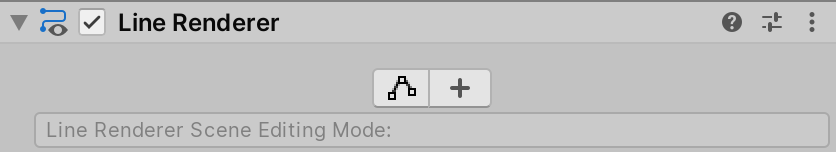
Use the Edit Points and Create Points buttons at the top of the Inspector to set the current Scene Editing Mode.
Click the Edit Points button to set the Scene Editing Mode to Edit Points. Click it again to set the Scene Editing Mode to None.
Click the Create Points button to set the Scene Editing Mode to Create Points. Click it again to set the Scene Editing Mode to None.
Scene Editing Mode: None
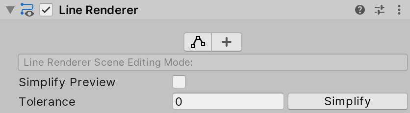
When no Scene Editing Mode is selected, you can configure and perform a simplification operation that removes unnecessary points from the Positions array.
The following controls are visible in the Inspector:
| Control | Description |
|---|---|
| Simplify Preview | Enable Simplify Preview to see a preview of the results of the simplification operation. |
| Tolerance | Set the amount by which the simplified line can deviate from the original line. A value of 0 results in no deviation, and therefore little or no simplification. Higher positive values result in more deviation from the original line, and therefore more simplification. The default value is 1. |
| Simplify | Click Simplify to reduce the number of elements in the Line Renderer’s Positions array. The simplification operation uses the Ramer-Douglas-Peucker algorithm to reduce the number of points, based on the Tolerance value. |
Scene Editing Mode: Edit Points

When the Scene Editing Mode is set to Edit Points, Unity represents each point in the Line Renderer’s Positions array as a yellow sphere in the Scene view. You can move the individual points using the Move tool.
The following controls are visible in the Inspector:
| Control | Description |
|---|---|
| Show Wireframe | When enabled, Unity draws a wireframe in the Scene view that visualizes the line. |
| Subdivide Selected | This button is enabled when you select two or more adjacent points. Pressing this button inserts a new point between the selected adjacent points. |
Scene Editing Mode: Create Points
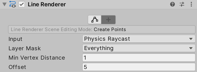
When the Scene Editing Mode is set to Create Points, you can click inside the Scene view to add new points to the end of the Line Renderer’s Positions array.
The following controls are visible in the Inspector:
| Control | Description | |
|---|---|---|
| Input | Set the input method you want to use to create points. | |
| Mouse position | Create points based on the mouse position in the Scene view. | |
| Physics Raycast | Create points based on a raycast into the Scene. Unity creates the point at the position where the raycast hits. | |
| Layer Mask | The layer maskA value defining which layers to include or exclude from an operation, such as rendering, collision or your own code. More info See in Glossary to use when performing a raycast. This property is visible only when Input is set to Physics Raycast. |
|
| Min Vertex Distance | When you drag the mouse to create points in the Scene view, the Line Renderer creates a new point when this distance from the last point is exceeded. | |
| Offset | The offset applied to created points. When Input is set to Mouse Position, Line Renderer applies the offset from the Scene cameraA component which creates an image of a particular viewpoint in your scene. The output is either drawn to the screen or captured as a texture. More info See in Glossary. When Input is set to Physics Raycast, Line Renderer applies the offset from the raycast normal. |
|
Properties

This section contains the following sub-sections:
- Line settings
- MaterialsAn asset that defines how a surface should be rendered, by including references to the Textures it uses, tiling information, Color tints and more. The available options for a Material depend on which Shader the Material is using. More info
See in Glossary - Lighting
- Probes
- Additional settings
Line settings
| Property | Function | |
|---|---|---|
| Loop | Enable this to connect the first and last positions of the line, and form a closed loop. | |
| Positions | The array of Vector3 points to connect. | |
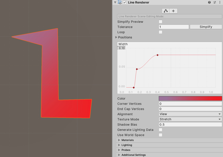
| Width | Define a width value, and a curve value to control the width of your line along its length. The curve is sampled at each vertex, so its accuracy is limited by the number of vertices in your line. The overall width of the line is controlled by the width value. |
|
| Color | Define a gradient to control the color of the line along its length. Unity samples colors from the Color gradient at each vertex. Between each vertex, Unity applies linear interpolation to colors. Adding more vertices to your line might give a closer approximation of a detailed gradient. |
|
| Corner Vertices | This property dictates how many extra vertices are used when drawing corners in a line. Increase this value to make the line corners appear rounder. | |
| End Cap Vertices | This property dictates how many extra vertices are used to create end caps on the line. Increase this value to make the line caps appear rounder. | |
| Alignment | Set the direction that the line faces. | |
| View | The line faces the Camera. | |
| TransformZ | The line faces the Z axis of its Transform componentA Transform component determines the Position, Rotation, and Scale of each object in the scene. Every GameObject has a Transform. More info See in Glossary. |
|
| Texture Mode | Control how the Texture is applied to the line. | |
| Stretch | Map the texture once along the entire length of the line. | |
| Tile | Repeat the texture along the line, based on its length in world units. To set the tiling rate, use Material.SetTextureScale. | |
| DistributePerSegment | Map the texture once along the entire length of the line, assuming all vertices are evenly spaced. | |
| RepeatPerSegment | Repeat the texture along the line, repeating at a rate of once per line segment. To adjust the tiling rate, use Material.SetTextureScale. | |
| Shadow Bias | Set the amount to move shadows away from the Light to remove shadowing artifacts cused by approximating a volume with billboarded geometry. | |
| Generate Lighting Data | If enabled, Unity builds the line geometry with normals and tangents included. This allows it to use Materials that use the Scene lighting. | |
| Use World Space | If enabled, the points are considered as world space coordinates. If disabled, they are local to the transform of the GameObject to which this component is attached. | |
Materials
The Materials section in the Line Renderer Inspector lists the Materials that the Line Renderer is using.
| Property | Function |
|---|---|
| Size | Specify the number of Materials in the Line Renderer. If you decrease the size of the list of Materials, Unity deletes the elements at the end of the list. |
| Element | A list of the Materials in the Line Renderer, in numeric order. The first element is always named Element 0. |
Lighting
The Lighting section contains properties for how this Line Renderer interacts with lighting in Unity.
| Property | Function | |
|---|---|---|
| Cast Shadows | Specify if and how the line casts shadows when a suitable Light shines on it. | |
| On | The line casts a shadow when a shadow-casting Light shines on it. | |
| Off | The line does not cast shadows. | |
| Two Sided | The line casts two-sided shadows from either side. EnlightenA lighting system by Geomerics used in Unity for lightmapping and for Realtime Global Illumination. More info See in Glossary and the Progressive LightmapperA tool in Unity that bakes lightmaps according to the arrangement of lights and geometry in your scene. More info See in Glossary do not support two-sided shadows. |
|
| Shadows Only | Shadows from the line are visible, but not the line itself. | |
| Receive Shadows | Enable this option to make the line display any shadows that are cast upon it. This is only supported when using the Progressive Lightmapper. | |
Probes
The Probes section contains properties relating to Light Probes and Reflection Probes.
| Property | Function | |
|---|---|---|
| Light Probes | Set how this Renderer receives light from the Light Probe system. For more information, see Light ProbesLight probes store information about how light passes through space in your scene. A collection of light probes arranged within a given space can improve lighting on moving objects and static LOD scenery within that space. More info See in Glossary. |
|
| Off | The Renderer doesn’t use any interpolated Light Probes. | |
| Blend Probes | The Renderer uses one interpolated Light Probe. This is the default value. | |
| Use Proxy Volume | The Renderer uses a 3D grid of interpolated Light Probes. | |
| Custom Provided | The Renderer extracts Light Probe shader uniform values from the MaterialPropertyBlock. | |
| Proxy Volume Override | Set a reference to another GameObject that has a Light Probe Proxy Volume component. This property is only visible when Light Probes is set to Use Proxy Volume. |
|
| Reflection Probes | Set how the Renderer receives reflections from the Reflection ProbeA rendering component that captures a spherical view of its surroundings in all directions, rather like a camera. The captured image is then stored as a Cubemap that can be used by objects with reflective materials. More info See in Glossary system. |
|
| Off | Disables Reflection Probes. Unity uses a skyboxA special type of Material used to represent skies. Usually six-sided. More info See in Glossary for reflection. |
|
| Blend Probes | Enables Reflection Probes. Blending occurs only between Reflection Probes. This is useful in indoor environments where the character may transition between areas with different lighting settings. | |
| Blend Probes and Skybox | Enables Reflection Probes. Blending occurs between Reflection Probes, or between Reflection Probes and the default reflection. This is useful for outdoor environments. | |
| Simple | Enables Reflection Probes, but no blending occurs between Reflection Probes when there are two overlapping volumes. | |
| Anchor Override | Set the Transform that Unity uses to determine the interpolation position when using the Light Probe or Reflection Probe systems. By default, this is the centre of the bounding box of the Renderer’s geometry. | |
Additional Settings
The Additional Settings contain additional properties.
| Property | Function | |
|---|---|---|
| Motion Vectors | Set whether to use motion vectors to track this Renderer’s per-pixel, screen-space motion from one frame to the next. You can use this information to apply post-processing effects such as motion blur. Note that not all platforms support motion vectors. See SystemInfo.supportsMotionVectors for more information. |
|
| Camera Motion Only | Use only Camera movement to track motion. | |
| Per Object Motion | Use a specific pass to track motion for this Renderer. | |
| Force No Motion | Do not track motion. | |
| Dynamic Occlusion | When Dynamic Occlusion is enabled, Unity culls this Renderer when it is blocked from a Camera’s view by a Static Occluder. Dynamic Occlusion is enabled by default. When Dynamic Occlusion is disabled, Unity does not cull this Renderer when it is blocked from a Camera’s view by a Static Occluder. Disable Dynamic Occlusion to achieve effects such as drawing the outline of a character behind a wall. See documentation on occlusion cullingA Unity feature that disables rendering of objects when they are not currently seen by the camera because they are obscured (occluded) by other objects. More info See in Glossary for more information. |
|
| Sorting Layer | The name of this Renderer’s Sorting Layer. | |
| Order in Layer | This Renderer’s order within a Sorting Layer. | |
Copyright © 2023 Unity Technologies
优美缔软件(上海)有限公司 版权所有
"Unity"、Unity 徽标及其他 Unity 商标是 Unity Technologies 或其附属机构在美国及其他地区的商标或注册商标。其他名称或品牌是其各自所有者的商标。
公安部备案号:
31010902002961