Single Pass Stereo rendering (Double-Wide rendering)
Single Pass Stereo rendering is a feature for PC and Playstation 4-based VR applications. It renders both left and right eye images at the same time into one packed Render Texture that is twice the width of a single eye texture. Unity renders the Scene twice using 2 draw calls for each GameObject that has a Renderer component, however, it only iterates through the Scene graph once when rendering for both the left and right eyes. During Single Pass Stereo rendering, both eyes share the work required by culling and shadow computation. There are also fewer graphics command state change switches, because the GPU renders each GameObject in a ping pong fashion (alternates rendering of objects between eyes).
Single Pass Stereo rendering allows the GPU to share culling for both eyes. The GPU only needs to iterate through all the GameObjects in the Scene once for culling purposes, and then renders the GameObjects that survived the culling process.
The comparison images below show the difference between normal VR rendering and Single Pass Stereo rendering.
Normal VR rendering:

Single-Pass Stereo VR rendering:

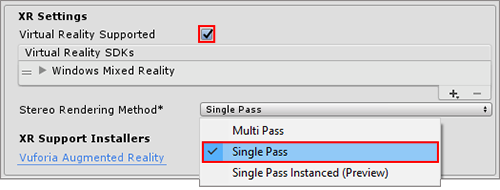
To enable this feature, open the Player settings (menu: Edit > Project Settings, then select the Player category). Then navigate to the XR Settings panel, ensure the Virtual Reality Supported checkbox is ticked, and select the Single Pass option from the Stereo Rendering Method dropdown.
Unity’s built-in rendering features and Standard Assets all support this feature. However, custom-built Shaders and Shaders downloaded from the Asset Store might need to be modified (for example, you might need to scale and offset screen space coordinates to access the appropriate half of the packed Render Texture) to add Single Pass Stereo rendering support.
Adding Single Pass Stereo rendering support to Shaders
Existing helper methods in UnityCG.cginc support Single Pass Stereo rendering. Whether your application is XR or not, you still need to perform transformations on vertices. For example, when creating any type of application, the vertices enter the vertex shader stage in model space and exit in clip space. The vertex shader must output clip space vertex coordinates. The set of vertices affected by the shader normally begins in model space before the vertex shader transforms them into clip space. However, in order for these vertices to arrive in clip space, the vertex shader first transforms them into world space and then to viewport space.
In the case of XR, there are multiple view matrices: one for both the left and right eye. You can use the built-in method UnityWorldToClipPos to ensure that Unity takes into consideration whether the calculation requires handling multiple view matrices. If you use theUnityWorldToClipPos method, the shader automatically performs the transformation calculation correctly, regardless of the platform your application is running on.
UnityCG.cginc also contains the following helper methods to assist you with authoring stereoscopic Shaders:
| Property | Parameters | Description |
|---|---|---|
| UnityStereoScreenSpaceUVAdjust(uv, sb) |
uv: UV texture coordinates. Either a float2 for a standard UV or a float4 for a packed pair of two UVs.sb: A float4 containing a 2D scale and 2D bias which the shader applies to the UV, with scale in xy and bias in zw. |
If UNITY_SINGLE_PASS_STEREO is defined, this returns the result of applying the scale and bias in sb to the texture coordinates in uv. Otherwise, this returns the texture coordinates unmodified. Use this to apply a per-eye scale and bias only when in Single Pass Stereo rendering mode. |
| UnityStereoTransformScreenSpaceTex(uv) |
uv: UV texture coordinates. Either a float2 for a standard UV or a float4 for a packed pair of two UVs. |
If UNITY_SINGLE_PASS_STEREO is defined, this returns the result of applying the current eye’s scale and bias to the texture coordinates in uv. Otherwise, this returns the texture coordinates unaltered. |
| UnityStereoClamp(uv, sb) |
uv: UV texture coordinates. Either a float2 for a standard UV or a float4 for a packed pair of two UVs. sb: A float4 containing a 2D scale and 2D bias which the shader applies to the UV, with scale in xy and bias in zw. |
If UNITY_SINGLE_PASS_STEREO is defined, this returns the result of applying the clamp to the x value, using the width, and bias, provided by sb, to the texture’s coordinates in uv. Otherwise returns the texture coordinates unmodified. Use this to apply a per-eye clamping in Single Pass Stereo rendering mode to avoid color bleeding between eyes. |
Shaders expose the constant in-built variable ‘unity_StereoEyeIndex’, so that Unity can perform eye-dependent calculations. The value of unity_StereoEyeIndex is 0 for left-eye rendering, and 1 for right-eye rendering.
Here is an example from UnityCG.cginc, demonstrating how you can useunity_StereoEyeIndex to modify screen space coordinates:
float2 TransformStereoScreenSpaceTex(float2 uv, float w)
{
    float4 scaleOffset = unity_StereoScaleOffset[unity_StereoEyeIndex];
    return uv.xy * scaleOffset.xy + scaleOffset.zw * w;
}
In most cases, you don’t need to modify your Shaders. However, there are situations in which you might need to sample a monoscopic Texture as a source for Single Pass Stereo rendering (for example, if you are creating a full-screen film grain or noise effect where the source image should be the same for both eyes, rather than packed into a stereoscopic image). In such situations, use ComputeNonStereoScreenPos() instead of ComputeScreenPos() to calculate locations from the full source Texture.
Post-processing effects
Post-processing effects require some extra work to support Single Pass Stereo rendering. Each post-processing effect runs once on the packed Render Texture (which contains both the left and right eye images), but applies all draw commands that run during the post-processing twice: once to the left-eye half of the destination Render Texture, and once to the right-eye half.
Post-processing effects do not automatically detect Single Pass Stereo rendering, so you need to adjust any reads of packed Stereo Render Textures so that they only read from the correct side for the eye being rendered. There are two ways to do this depending on how your post-processing effect is being rendered:
- Using Graphics.Blit()
- Mesh-based drawing
Without the above-mentioned adjustments, each draw command reads the whole of the source Render Texture (containing both the left and right eye views), and outputs the entire image pair to both the left and right eye sides of the output Render Texture, resulting in incorrect duplication of the source image in each eye.
This happens when using Graphics.Blit or a fullscreen polygon with a Texture map to draw each post-processing effect . Both methods reference the entire output of the previous post-processing effect in the chain. When referring to an area in a packed stereo Render Texture, they reference the whole packed Render Texture instead of just the relevant half of it.
Graphics.Blit()
Post-processing effects rendered with Blit() do not automatically reference the correct part of packed stereo Render Textures. By default, they refer to the entire texture. This incorrectly stretches the post-processing effect across both eyes.
For Single Pass Stereo rendering using Blit(), texture samplers in Shaders have an additional auto-calculated variable which refers to the correct half of a packed stereo Render Texture, depending on the eye being drawn. The variable contains scale and offset values that allow you to transform your target coordinates to the correct location.
To access this variable, declare a half4 in your Shader with the same name as your sampler, and add the suffix _ST (see below for a code example of this). To adjust UV coordinates, pass in your _ST variable to scaleAndOffset and use UnityStereoScreenSpaceUVAdjust(uv, scaleAndOffset). This method compiles to nothing in non-Single Pass Stereo builds, meaning that shaders modified to support this mode are still compatible with non-Single Pass Stereo builds.
The following examples demonstrate what you need to change in your fragment shader code to support Single Pass Stereo rendering.
Without stereo rendering:
uniform sampler2D _MainTex;

fixed4 frag (v2f_img i) : SV_Target
{
    fixed4 myTex = tex2D(_MainTex, i.uv);
    ...
}
With stereo rendering:
uniform sampler2D _MainTex;
half4 _MainTex_ST;

fixed4 frag (v2f_img i) : SV_Target
{
    fixed4 myTex = tex2D(_MainTex, UnityStereoScreenSpaceUVAdjust(i.uv, _MainTex_ST));
    ...
}
Mesh-based drawing
Rendering Post-processing effects using meshes (for example, by drawing a quadrilateral in immediate mode using the low level graphics API) also need to adjust the UV coordinates on the target Texture when rendering each eye. To adjust your coordinates in these circumstances, use UnityStereoTransformScreenSpaceTex(uv). This method correctly adjusts for packed stereo Render Textures in Single Pass Stereo rendering mode, and automatically compiles for non-packed Render Textures if you have disabled Single Pass Stereo rendering mode. However, if you intend to use a Shader both for packed and unpacked Render Textures in the same mode, you need to have two separate Shaders.
Screen space effects
Screen space effects are visual effects that are drawn over a pre-rendered image. Examples of screen space effects include ambient occlusion, depth of field, and bloom.
For example, imagine a screen space effect that requires an image to be drawn over the screen (perhaps you are drawing some kind of dirt spattered on the screen). Instead of applying the effect over the entire output display, which would stretch the dirt image across both eyes, you need to apply it twice: once for each eye. In cases like this, you need to convert from using texture coordinates that reference the whole packed Render Texture, to coordinates that reference each eye.
The following code examples show a Surface Shader that repeats an input Texture (called _Detail) 8 x 6 times across the output image. In the second example, the shader transforms the destination coordinates in Single Pass Stereo mode to refer to the part of the output Texture that represents the eye currently being rendered.
Example 1: Detail Texture with no Single-Pass Stereo support
void surf(Input IN, inout SurfaceOutput o)
{
    o.Albedo = tex2D(_MainTex, IN.uv_MainTex).rgb;
    float2 screenUV = IN.screenPos.xy / IN.screenPos.w;
    screenUV *= float2(8,6);
    o.Albedo *= tex2D(_Detail, screenUV).rgb * 2;
}
Example 2: Detail Texture with Single-Pass Stereo support
void surf(Input IN, inout SurfaceOutput o)
{
    o.Albedo = tex2D(_MainTex, IN.uv_MainTex).rgb;
    float2 screenUV = IN.screenPos.xy / IN.screenPos.w;
    #if UNITY_SINGLE_PASS_STEREO
    // If Single-Pass Stereo mode is active, transform the
    // coordinates to get the correct output UV for the current eye.
    float4 scaleOffset = unity_StereoScaleOffset[unity_StereoEyeIndex];
    screenUV = (screenUV - scaleOffset.zw) / scaleOffset.xy;
    #endif
    screenUV *= float2(8,6);
    o.Albedo *= tex2D(_Detail, screenUV).rgb * 2;
}
- 2018–08–16 Page published with limited editorial review
- New in Unity 2017.3 NewIn20173
Copyright © 2023 Unity Technologies
优美缔软件(上海)有限公司 版权所有
"Unity"、Unity 徽标及其他 Unity 商标是 Unity Technologies 或其附属机构在美国及其他地区的商标或注册商标。其他名称或品牌是其各自所有者的商标。
公安部备案号:
31010902002961