Placing Light Probes
To place Light Probes in your scene, you must use a GameObject with a Light Probe Group component attached. You can add a Light Probe Group component from the menu: Component -> Rendering -> Light Probe Group.
The Light Probe Group component can be added to any object in the scene, however it’s best to add it to a new empty GameObject.
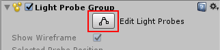
The Light Probe Group has its own Edit Mode which can be turned on or off. To add, move, or delete light probes, you must switch the Light Probe Group’s edit mode on by pressing the Edit Light Probes button:
When you are using the Edit Light Probes mode, you can manupulate individual light probes as in a similar way to GameObjects, however the individual probes are not GameObjects - they are stored as a set of points in the Light Probe Group component.
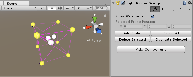
When you begin editing a new Light Probe Group, you will start off with a default formation of eight probes arranged in a cube, as shown below:
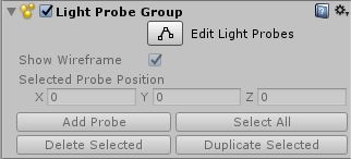
You can now use the controls in the Light Probe Group inspector to add new probe positions to the group. The probes appear in the scene as yellow spheres which can be positioned in the same manner as GameObjects. You can also select and duplicate individual probes or in groups, by using the usual “duplicate” keyboard shortcut (ctrl+d/cmd+d).
Remember to switch the Light Probe Group edit mode off once you’ve finished editing the probes, or you will find you cannot move or manipulate normal GameObjects!
Choosing Light Probe positions
Unlike lightmaps, which usually have a continuous resolution across the surface of an object, the resolution of the light probe information is entirely defined by how closely packed you choose to position the probes.
To optimise the amount of data that is stored by light probes, and the amount of computation done while the game is playing, you should generally attempt to place as few light probes as possible. However, you should also place enough probes that changes in light from one space to another are recorded at a level that is acceptable to you. This means you might place light probes in a more condensed pattern around areas that have complex or highly contrasting light, and you might place them in a much more spread out pattern over areas where the light does not significantly change.
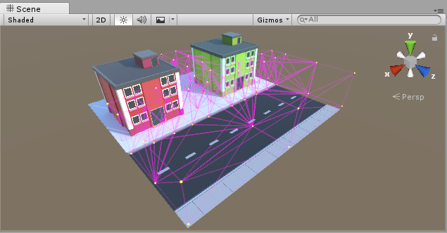
In the example above, the probes are placed more densely near and between the buildings where there is more contrast and color variation, and less densely along the road, where the lighting does not significantly change.
The simplest approach to positioning probes is to arrange them in a regular 3D grid pattern. While this setup is simple and effective, it is likely to consume more memory than necessary, and you may have lots of redunant probes. For example, in the scene above, if there were lots of probes placed along the road it would be a waste of resources. The light does not change much along the length of the road, so many probes would be storing almost identical lighting data to their neighbouring probes. In situations like this, it is much more efficient to interpolate this lighting data between fewer more spread-out probes.
Light probes individually do not store a large amount of information. From a technical perspective, each probe is a spherical, panoramic HDR image of the view from the sample point, encoded using Spherical Harmonics L2 which is stored as 27 floating point values. However in large scenes with hundreds of probes they can add up, and having unnecessarily densely packed probes can result in large amounts of wasted memory in your game.
Creating a volume
Even if your gameplay takes place on a 2D plane (for example, cars driving around on a road surface), your light probes must form a 3D volume.
This means you should have at least two vertical “layers” of points in your group of probes.
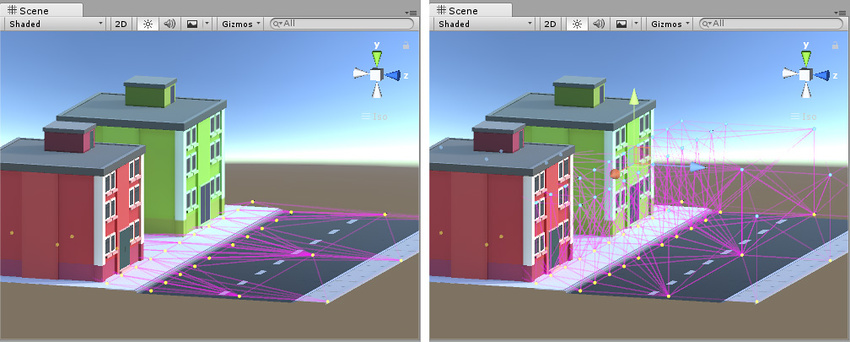
In the example below, you can see on the left the probes are arranged only across the surface of the ground. This will not result in good lighting because the light probe system will not be able to calculat sensible tetrahedral volumes from the probes.
On the right, the probes are arranged in two layers, some low to the ground and others higher up, so that together they form a 3D volume made up of lots of individual tetrahedra. This is a good layout.
Light Probe placement for dynamic GI
Unity’s realtime GI allows moving lights to cast dynamic bounced light against your static scenery. However, you can also receive dynamic bounced light from moving lights on moving GameObjects when you are using llight probes.
Light Probes therefore perform two very similar but distinct functions - they store static baked light, and at runtime they represent sampling points for dynamic realtime global illumination (GI, or bounced light) to affect the lighting on moving objects.
Therefore, if you are using dynamic moving lights, and want realtime bounced light on your moving GameObjects, this may have implications on your choice of where you place your light probes, and how densely you group them.
The main point to consider in this situation is that in large areas of relatively unchanging static light you might have placed only a few probes - because the light does not change across a wide area. However, if you plan to have moving lights within this area, and you want moving objects to receive bounced light from them, you will need a more dense network of light probes within the area so that there is a high enough level of accuracy to match your light’s range and style.
How densely placed your probes need to be will vary depending on the size and range of your lights, how fast they move, and how large the moving objects are that you want to receive bounced light.
Light Probe placement problems
Your choice of light probe positions must take into account that the lighting will be interpolated between sets of probes. Problems can arise if your probes don’t adequately cover the changes in lighting across your scene.
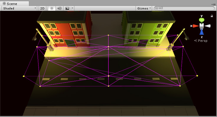
The example below shows a night-time scene with two bright street lamps on either side, and a dark area in the middle. If light probes are only placed near the street lamps, and none in the dark area, the lighting from the lamps will “bleed” across the dark gap, on moving objects. This is because the lighting is being interpolated from one bright point to another, with no information about the dark area in-between.

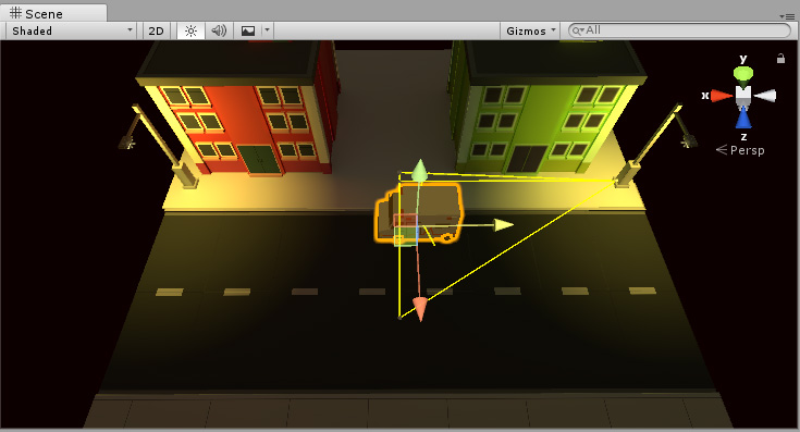
If you are using realtime or mixed lights, this problem may be less noticable, because only the indirect light will bleed across the gap. The problem is more noticable if you are using fully baked lights, because in this situation the direct light on moving objects is also interpolated from the light probes. In this example scene the two lamps are baked, so moving objects get their direct light from light probes. Here you can see the result - a moving object (the ambulance) remains brightly lit while passing through the dark area, which is not the desired effect. The yellow wireframe tetrahedron shows that the interpolation is occuring between one brightly lit end of the street to the other.

This is an undesired effect - the ambulance remains brightly lit while passing through a dark area, because no light probes were placed in the dark area.
To solve this, you should place more probes in the dark area, as shown below:
Now the scene has probes in the dark area too. And as a result, the moving ambulance takes on the darker lighting as it travels from one side of the scene to the other.
The ambulance now takes on the darker lighting in the centre of the scene, as desired.
2017–06–08 Page published with no editorial review
Light Probes updated in 5.6
Copyright © 2023 Unity Technologies
优美缔软件(上海)有限公司 版权所有
"Unity"、Unity 徽标及其他 Unity 商标是 Unity Technologies 或其附属机构在美国及其他地区的商标或注册商标。其他名称或品牌是其各自所有者的商标。
公安部备案号:
31010902002961