Spatial Mapping Renderer
The Spatial Mapping Renderer component provides a visual representation of Spatial MappingThe process of mapping real-world surfaces into the virtual world. More info
See in Glossary Surfaces. This is useful for visually debugging Surfaces and adding visual effects to the environment.
The system periodically sends data to the Spatial Mapping Renderer component about changes in physical space. Each time the component is notified of these changes by the Spatial Mapping system, it bakes the returned Surface data into GameObjectsThe fundamental object in Unity scenes, which can represent characters, props, scenery, cameras, waypoints, and more. A GameObject’s functionality is defined by the Components attached to it. More info
See in Glossary that contain both Mesh FilterA mesh component that takes a mesh from your assets and passes it to the Mesh Renderer for rendering on the screen. More info
See in Glossary and Mesh RendererA mesh component that takes the geometry from the Mesh Filter and renders it at the position defined by the object’s Transform component. More info
See in Glossary components. The Spatial Mapping Renderer component manages the lifetime of these Surface GameObjects. This means that it handles creating, updating, and destroying the Surface GameObject MeshThe main graphics primitive of Unity. Meshes make up a large part of your 3D worlds. Unity supports triangulated or Quadrangulated polygon meshes. Nurbs, Nurms, Subdiv surfaces must be converted to polygons. More info
See in Glossary Renderers in the SceneA Scene contains the environments and menus of your game. Think of each unique Scene file as a unique level. In each Scene, you place your environments, obstacles, and decorations, essentially designing and building your game in pieces. More info
See in Glossary.

Render Settings
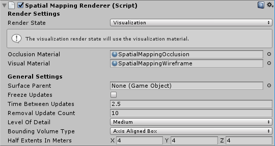
The table below lists all unique Render Settings available for the Spatial Mapping Renderer component.
| Setting | Description | |
|---|---|---|
| Render State | All Surface GameObjects take their material from the Render State setting. When you change the Render State setting (for example, by script during run time), all Surface GameObjects’ render Materials change to those of the chosen Render State setting. This reduces the number of draw calls, which in turn improves the rendering performance. Using a shared material also reduces the amount of memory used by the application during rendering. Select one of the three options to render Surfaces. See Render State, below, for more information. |
|
| Occlusion | Apply the Material defined in Occlusion Material. This is a transparent Material which hides GameObjects behind real world Surfaces. See Visual and Occlusion Materials, below, for more information. Note: This enables all of a Surface’s Mesh Renderers, overriding any other setting. |
|
| Visualisation | Apply the Material defined in Visualization Material for visualizing the Spatial Mapping Surfaces (usually a wireframe Material) in your environment. See Visual and Occlusion Materials, below, for more information. Note: This enables all of a Surface’s Mesh Renderers, overriding any other setting. |
|
| None | Choose to disable all the Mesh Renderers assigned to the Spatial Mapping Surfaces. | |
| Occlusion Material | The material you select here applies when the Spatial Mapping Renderer’s Render State is set to Occlusion. The default is the built-in SpatialMappingOcclusion material. | |
| Visual Material | The material you select here is the Visual Material that applies when the Spatial Mapping Renderer Render State is set to Visualization. The default is the built-in SpatialMappingWireframe material. | |
General Settings
SpatialMapping Components General Settings
The settings below are common to both Spatial Mapping Renderer and Spatial Mapping Collider components.
| Setting | Description |
|---|---|
| Surface Parent | Select the Surface Parent GameObject that you want Surface GameObjects generated by Spatial Mapping components to inherit from. Leave this as None(Game Object), to automatically generate a Surface Parent GameObject. |
| Freeze Updates | Check this box to stop the component querying the system for Surface changes. Note: Each Spatial Mapping component periodically queries the Spatial Mapping data for Surface changes in physical space. Querying and baking Surfaces costs memory, performance, and power. For environments that you expect to be mostly static, we recommend that you allow users to look around the environment for a duration of time without updating the Surface GameObjects. If you expect the environment in your simulation to be mostly static and unchanging (like a board game), you can scan as much Surface data as you need when your application starts, and then set the Freeze Updates property to true to prevent further updates. This increases performance slightly and consumes less power. |
| Time Between Updates | The time in decimal format seconds (for example, 3.7 or 4.6) between queries for Surface changes in physical space. The default is 2.5 seconds. Note that the more regular the queries, the higher the cost in memory, performance, and power. |
| Removal Update Count | The number of updates before a Surface GameObject is removed by the system. You can think of an update as a frame in this case. The default is 10 updates. Note: The removal update countdown begins when Spatial Mapping notifies the component that a Surface GameObject is no longer in the SurfaceObserver’s bounding volume (in that it is no longer within the defined area that the system reports on). This setting allows you to specify the number of updates that should happen after this event before Spatial Mapping removes the Surface GameObject. |
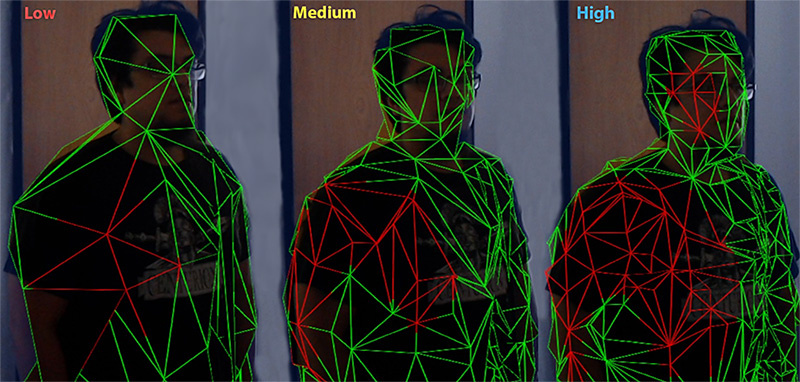
| Level of Detail | The quality of the Mesh that the component generates (Low, Medium, or High). The default quality is Medium. The higher the quality, the more refined and accurate the generated ColliderAn invisible shape that is used to handle physical collisions for an object. A collider doesn’t need to be exactly the same shape as the object’s mesh - a rough approximation is often more efficient and indistinguishable in gameplay. More info See in Glossary or rendered Mesh. Using lower quality settings results in a lower cost in performance and power consumption. See the image below this table for an example of the three Level Of DetailThe Level Of Detail (LOD) technique is an optimization that reduces the number of triangles that Unity has to render for a GameObject when its distance from the Camera increases. Each LOD level has either a Mesh with a Mesh Renderer component (Mesh LOD level) or a Billboard AssetAn asset that is a collection of pre-rendered images of a more complicated Mesh intended for use with the Billboard Renderer, in order to render an object at some distance from a Camera at a lower level of detail (LOD) to save on rendering time. More info See in Glossary with a Billboard RendererRenders Billboard Assets, either from a pre-made Asset (exported from SpeedTree) or from a custom-created file that you create using a script at runtime or from a custom editor, for example. More info See in Glossary component (Billboard LOD level). Typically a single GameObject has three or four Mesh LOD levels and one optional Billboard LOD level to represent the same GameObject with decreasing detail in the geometry. More info See in Glossary modes. |
| Bounding Volume Type | The component’s bounding volume area shape, in which the application receives Spatial Mapping data. This can be either a Sphere or Axis Aligned Box. The default is Axis Aligned Box. Note: The bounding volume is the defined area about which the system reports physical Surface changes and limits the extents of the Spatial Mapping Mesh. |
| Size In Meters | The size of the bounding volume used by component (in meters). Configure Sphere by radius; the default radius is 2 meters. Configure Axis Aligned Box by its extents; the default is a Vector3 (4,4,4). Note: The observer’s bounding volume is the defined area about which Spatial Mapping reports physical Surface changes. |
Level of Detail
Both Spatial Mapping components allow you to specify one of three Levels of Detail for each component’s generated spatial meshes (Low, Medium, or High) as depicted in the image below.

When possible, set the Level of Detail setting for Spatial Mapping Colliders to Low. This increases performance and reduces power usage when calculating collisionA collision occurs when the physics engine detects that the colliders of two GameObjects make contact or overlap, when at least one has a rigidbody component and is in motion. More info
See in Glossary intersections. However, setting Level of Detail to Low can negatively affect the visual effect of your application,
Using the Spatial Mapping Renderer
Render State
This component provides an easy way to change the material on all generated Surfaces dynamically. Unity provides two pre-built Material types for you to use:
Occlusion Material
This makes the GameObject appear transparent, but holograms are not visible through the GameObject. For example, this might be useful if you require a real-world desk to conceal an in-game holographicThe former name for Windows Mixed Reality. More info
See in Glossary object placed underneath it.
Visual Material
This is a wireframe Material that Unity applies to all Surfaces in the Spatial Mapping Renderer component. With the default Wireframe ShaderA small script that contains the mathematical calculations and algorithms for calculating the Color of each pixel rendered, based on the lighting input and the Material configuration. More info
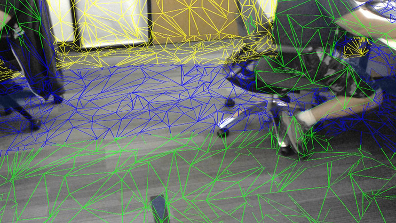
See in Glossary, the colors of the wireframe represent real-world distances. This is usually the most useful option for debugging, but you can also use it for visual effects. The Shader uses color mapping to indicate distance; the table below shows this color mapping:
| Distance from HoloLens | Color |
|---|---|
| 0 to 1 meters | Black |
| 1 to 2 meters | Red |
| 2 to 3 meters | Green |
| 3 to 4 meters | Blue |
| 4 to 5 meters | Yellow |
| 5 to 6 meters | Cyan |
| 6 to 7 meters | Magenta |
| 7 to 8 meters | Maroon |
| 8 to 9 meters | Teal |
| 9 to 10 meters | Orange |
| 10 meters or greater | White |

When you assign a new Material to either the Visual Material or Occlusion Material, the Material of your Surface GameObjects does not automatically change. To apply the new Material to all Surfaces, you need to set the Render State to the Material you have changed (Visual Material or Occlusion Material).
If you only assign the Occlusion Material or Visual Material properties in Render State from the Unity Editor (directly on the GameObject in your scene), Spatial Mapping destroys them at the same time as the Spatial Mapping Renderer component. However, Spatial Mapping doesn’t destroy any Occlusion or Visual Materials assigned or changed through script with the component, so you will need to destroy them manually.
The code snippet below changes the Material that Spatial Mapping applies to all Surface GameObjects dynamically at run time.
SpatialMappingRenderer renderer = spatialMappingGameObject.AddComponent<SpatialMappingRenderer>();
renderer.visualMaterial = new Material(Shader.Find("VR/SpatialMapping/Wireframe"));
renderer.renderState = SpatialMappingRenderer.RenderState.Visualization;
Surface GameObjects
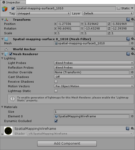
The Spatial Mapping Renderer component creates its own separate set of Surface GameObjects during run time. These appear in your Scene parented to a Surface Parent GameObject:

When a Spatial Mapping Renderer generates Surface GameObjects, they contain the following component
A shared MaterialAn asset that defines how a surface should be rendered, by including references to the Textures it uses, tiling information, Color tints and more. The available options for a Material depend on which Shader the Material is using. More info
See in Glossary (this is either a Visualization or Occlusion Material, depending on the Render State setting)

If you add multiple Spatial Mapping Renderer components to your Scene, each component generates its own set of Surface GameObjects. For example, if you have two GameObjects with Spatial Mapping Renderer components, then your Scene contains two sets of Surface GameObjects: one generated by each component at run time. This is important to keep in mind for optimization purposes.
2018–05–01 Page published with editorial review
Spatial Mapping for Hololens documentation updated in 2017.3