Ejemplos del Vertex y Fragment Shader
Esta página contiene más ejemplos de programas vertex y fragment. Para una introducción básica a shaders, ver los tutoriales acerca de shaders: Parte 1 y Parte 2. Para una manera fácil de escribir shaders de materiales regulares, ver Surface Shaders.
Usted puede descargar los ejemplos mostrados abajo como un proyecto zipped de Unity, aquí.
Configurando la escena
Si usted no es familiar con la Scene View, Hierarchy View, Project View e Inspector de Unity, ahora sería un buen momento para leer las primeras pocas secciones del manual, comenzando con Unity Basics.
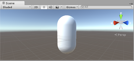
El primer paso es crear algunos objetos que a usted va a utilizar para probar sus shaders. Seleccione Game Object > 3D Object > Capsule en el menú principal. Luego posicione la cámara para que muestre su cápsula. Haga doble click en la cápsula en la jerarquía para enfocar la scene view (vista de escena) en este, luego seleccione el objeto de la Cámara Principal y haga click en Game object > Align with View desde el menú principal.
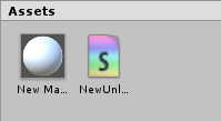
Cree un nuevo Material al seleccionar Create > Material desde el menú en la ventana del Proyecto. Un nuevo material llamado New Material va a aparecer en la Vista del Proyecto.

Creando un Shader
Ahora cree un nuevo asset Shader de una manera similar. Seleccione Create > Shader > Unlit Shader desde el menú en la ventana del Proyecto. Esto crea un shader básico que solamente muestra una textura sin alguna iluminación.
Otras entradas en el menú Create > Shader crean barebone shaders u otros tipos, por ejemplo un surface shader básico.
En-lanzando el Mesh, Material y Shader
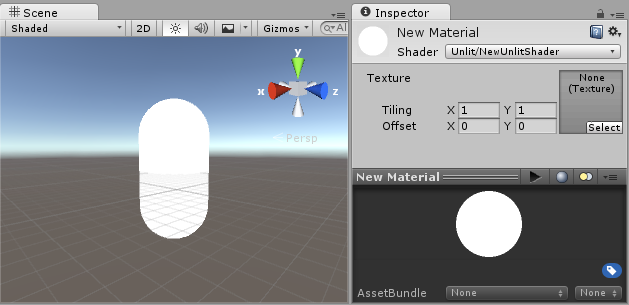
Haga que el material utilice el shader vía el inspector o simplemente arrastre el shader asset sobre el asset del material en la vista del proyecto. El inspector del material va a mostrar una esfera blanca cuando utilice este shader.

Ahora arrastre el material a su objeto mesh ya sea en la vista de Escena o Jerarquía. Alternativamente, seleccione el objeto, y en el inspector haga que utilice el material en la ranura Materials del componente Mesh Renderer.
Con estas cosas configuradas, usted ahora puede comenzar a mirar el código shader, y verá los resultados de sus cambios al shader en la cápsula en la vista de escena.
Partes principales del Shader
Para comenzar a examinar el código del shader, haga doble click en el asset shader en la Ventana del Proyecto. El código del shader va a abrirse en su editor de script (MonoDevelop o Visual Studio).
El shader comienza con este código:
Shader "Unlit/NewUnlitShader"
{
    Properties
    {
        _MainTex ("Texture", 2D) = "white" {}
    }
    SubShader
    {
        Tags { "RenderType"="Opaque" }
        LOD 100

        Pass
        {
            CGPROGRAM
            #pragma vertex vert
            #pragma fragment frag
            // make fog work
            #pragma multi_compile_fog

            #include "UnityCG.cginc"

            struct appdata
            {
                float4 vertex : POSITION;
                float2 uv : TEXCOORD0;
            };

            struct v2f
            {
                float2 uv : TEXCOORD0;
                UNITY_FOG_COORDS(1)
                float4 vertex : SV_POSITION;
            };

            sampler2D _MainTex;
            float4 _MainTex_ST;

            v2f vert (appdata v)
            {
                v2f o;
                o.vertex = UnityObjectToClipPos(v.vertex);
                o.uv = TRANSFORM_TEX(v.uv, _MainTex);
                UNITY_TRANSFER_FOG(o,o.vertex);
                return o;
            }

            fixed4 frag (v2f i) : SV_Target
            {
                // sample the texture
                fixed4 col = tex2D(_MainTex, i.uv);
                // apply fog
                UNITY_APPLY_FOG(i.fogCoord, col);
                return col;
            }
            ENDCG
        }
    }
}
Este shader inicial no se ve muy simple! Pero no se preocupe, nosotros iremos sobre cada parte paso-a-paso.
Veamos las partes principales de nuestro shader simple.
Shader
El comando Shader contiene un string con el nombre de el Shader. Usted puede utilizar caracteres de barra inclinada “/” para colocar su shader en sub-menús cuando seleccione su shader en el inspector del Material.
Propiedades
El bloque de Properties contiene variable shader (texturas, colores etc.) que serán guardadas como parte del Material, y mostrado en el inspector del material. En nuestra plantilla del unlit shader, hay una sola propiedad de textura declarada.
SubShader
Un Shader puede contener uno o más SubShaders, que son principalmente utilizadas para implementar shaders para diferentes capacidades de GPU. En este tutorial a nosotros no nos preocupa mucho esto, por lo que todo nuestros shaders van a contener solamente un SubShader.
Pass
Cada SubShader está compuesto de un número de passes, y cada Pass representa una ejecución del código del Vertex y Fragment para el mismo objeto renderizado con el material del shader. Muchos shaders simples utilizan solamente un pass, pero shaders que interactúan con la iluminación podrían necesitar más (ver ver Lighting Pipeline para detalles). Los comandos dentro del Pass típicamente configuran el estado de la función fija, for ejemplo los modos de mezcla (blending modes).
CGPROGRAM .. ENDCG
These keywords surround portions of HLSL code within the vertex and fragment shaders. Typically this is where most of the interesting code is. See vertex and fragment shaders for details.
Un Simple Unlit Shader
La plantilla del unlit shader hace unas pocas más cosas que serían absolutamente necesitadas para mostrar un objeto con una textura. Por ejemplo, soporta Fog (niebla), y campos de textura tilling/offset en el material. Simplifiquemos el shader a su mínimo, y agreguemos más comentarios:
Shader "Unlit/SimpleUnlitTexturedShader"
{
    Properties
    {
        // we have removed support for texture tiling/offset,
        // so make them not be displayed in material inspector
        [NoScaleOffset] _MainTex ("Texture", 2D) = "white" {}
    }
    SubShader
    {
        Pass
        {
            CGPROGRAM
            // use "vert" function as the vertex shader
            #pragma vertex vert
            // use "frag" function as the pixel (fragment) shader
            #pragma fragment frag

            // vertex shader inputs
            struct appdata
            {
                float4 vertex : POSITION; // vertex position
                float2 uv : TEXCOORD0; // texture coordinate
            };

            // vertex shader outputs ("vertex to fragment")
            struct v2f
            {
                float2 uv : TEXCOORD0; // texture coordinate
                float4 vertex : SV_POSITION; // clip space position
            };

            // vertex shader
            v2f vert (appdata v)
            {
                v2f o;
                // transform position to clip space
                // (multiply with model*view*projection matrix)
                o.vertex = mul(UNITY_MATRIX_MVP, v.vertex);
                // just pass the texture coordinate
                o.uv = v.uv;
                return o;
            }

            // texture we will sample
            sampler2D _MainTex;

            // pixel shader; returns low precision ("fixed4" type)
            // color ("SV_Target" semantic)
            fixed4 frag (v2f i) : SV_Target
            {
                // sample texture and return it
                fixed4 col = tex2D(_MainTex, i.uv);
                return col;
            }
            ENDCG
        }
    }
}
El Vertex Shader es un programa que corre en cada vértice del modelo 3D. A menudo no hace nada interesante en particular. Aquí solamente se transforma la posición vertex del espacio del objeto a algo llamado “clip space” (espacio del clip", el cual es utilizado por el GPU para rasterizar el objeto en la pantalla. Nosotros también pasamos la coordenada de textura input sin modificar - la necesitaremos para muestrar la textura al fragment shader.
El Fragment Shader es un programa que corre en cada uno de los pixeles que el objeto ocupa en pantalla, y usualmente es utilizado para calcular y mostrar el color de cada pixel. Usualmente hay millones de pixeles en la pantalla, y los fragment shaders son ejecutados para todos de ellos! Optimizar los fragment shaders es una parte importante en el rendimiento general del juego.
Algunas variables o definiciones de funciones se sigue por un Semantic Signifier - por ejemplo : POSITION or : SV_Target. Estos Semantics Signifiers comunican el “significado” de estas variables al GPU. Ver la página de shader semantics por detalles.
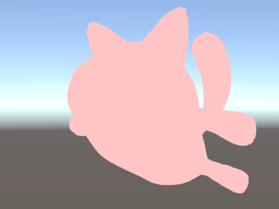
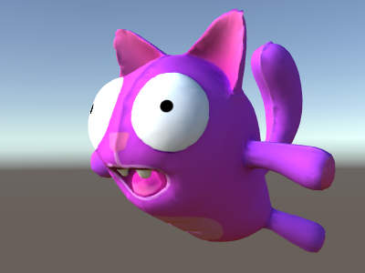
Cuando se utilice en un modelo lindo con una textura linda, nuestro shader simple se ve bastante bien!

Un Shader aun más simple, de un Solo Color
Simplifiquemos el shader aun más – haremos un shader que dibuje el objeto completo en un solo color. Esto no es bastante útil, pero ey! estamos aprendiendo aquí.
Shader "Unlit/SingleColor"
{
    Properties
    {
        // Color property for material inspector, default to white
        _Color ("Main Color", Color) = (1,1,1,1)
    }
    SubShader
    {
        Pass
        {
            CGPROGRAM
            #pragma vertex vert
            #pragma fragment frag

            // vertex shader
            // this time instead of using "appdata" struct, just spell inputs manually,
            // and instead of returning v2f struct, also just return a single output
            // float4 clip position
            float4 vert (float4 vertex : POSITION) : SV_POSITION
            {
                return mul(UNITY_MATRIX_MVP, vertex);
            }

            // color from the material
            fixed4 _Color;

            // pixel shader, no inputs needed
            fixed4 frag () : SV_Target
            {
                return _Color; // just return it
            }
            ENDCG
        }
    }
}
Esta vez en vez de utilizar structs para input (appdata) y output (v2f), las funciones del shader simplemente explican en detalle los inputs manualmente. De ambas maneras funciona, y la que usted escoja utilizar depende en su estilo de código y preferencias.
Utilizando Mesh Normals por diversión y para beneficio
Comencemos con un shader que muestre las normales del mesh en espacio del mundo. Sin más preámbulos:
Shader "Unlit/WorldSpaceNormals"
{
    // no Properties block this time!
    SubShader
    {
        Pass
        {
            CGPROGRAM
            #pragma vertex vert
            #pragma fragment frag
            // include file that contains UnityObjectToWorldNormal helper function
            #include "UnityCG.cginc"

            struct v2f {
                // we'll output world space normal as one of regular ("texcoord") interpolators
                half3 worldNormal : TEXCOORD0;
                float4 pos : SV_POSITION;
            };

            // vertex shader: takes object space normal as input too
            v2f vert (float4 vertex : POSITION, float3 normal : NORMAL)
            {
                v2f o;
                o.pos = UnityObjectToClipPos(vertex);
                // UnityCG.cginc file contains function to transform
                // normal from object to world space, use that
                o.worldNormal = UnityObjectToWorldNormal(normal);
                return o;
            }

            fixed4 frag (v2f i) : SV_Target
            {
                fixed4 c = 0;
                // normal is a 3D vector with xyz components; in -1..1
                // range. To display it as color, bring the range into 0..1
                // and put into red, green, blue components
                c.rgb = i.worldNormal*0.5+0.5;
                return c;
            }
            ENDCG
        }
    }
}
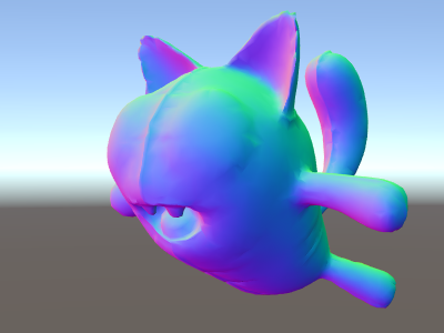
Además de resultar en colores bonitos, las normales son utilizadas para todo tipo de efectos de gráficas – iluminación, reflejos, siluetas y así.
En el shader de arriba, nosotros comenzamos a utilizar uno de los includes de los archivos shader integrados en Unity. Aquí, UnityCG.cginc fue utilizado, y contiene una función útil UnityObjectToWorldNormal. También hemos utilizado la función de utilidad UnityObjectToClipPos, que transforma el vértice desde el espacio del objeto a la pantalla. Esto hace que el código sea más fácil de leer y sea más eficiente bajo ciertas circunstancias.
Hemos visto que los datos pueden ser pasados desde el vertex al fragment shader en algo llamado “interpolators” ( o aveces llamado “varyings”). En el lenguaje de shading HLSL estas son típicamente etiquetadas con una semántica TEXCOORDn, y cada una de ellas pueden estar hasta en un vector de 4 componentes (mirar la página de semantics para detalles).
También, nosotros hemos aprendido una técnica simple en cómo visualizar vectores normalizados (en una rango de –1.0 a +1.0) como colores: simplemente multiplíquelos por la mitad y agregue la mitad. Vea más ejemplos de visualización de datos del vértice en la página vertex program inputs.
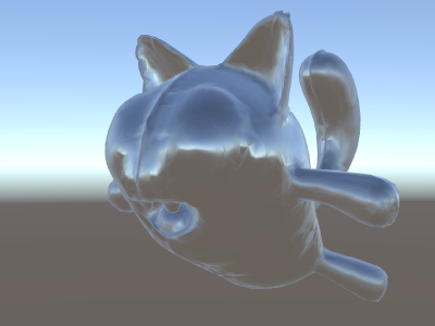
Reflejos del entorno utilizando Normales del espacio del mundo
Cuando un Skybox es utilizado en la escena como una fuente de reflejos (ver Lighting Window), entonces esencialmente un Reflection Probe “por defecto” es creado, conteniendo los datos del skybox. Un reflection probe es internamente una textura Cubemap; nosotros extenderemos las normales del espacio del mundo shader de arrhiba para mirar más en detalle.
El código está comenzando a involucrarse un poco ya. Desde luego, si usted quiere shaders que automáticamente funcionen con luces, sombras, reflejos y demás del sistema de iluminación, hay una manera más fácil de utilizar Surface Shaders. Este ejemplo tiene el objetivo de mostrarle cómo utilizar partes del sistema de iluminación de una manera “manual”.
Shader "Unlit/SkyReflection"
{
    SubShader
    {
        Pass
        {
            CGPROGRAM
            #pragma vertex vert
            #pragma fragment frag
            #include "UnityCG.cginc"

            struct v2f {
                half3 worldRefl : TEXCOORD0;
                float4 pos : SV_POSITION;
            };

            v2f vert (float4 vertex : POSITION, float3 normal : NORMAL)
            {
                v2f o;
                o.pos = UnityObjectToClipPos(vertex);
                // compute world space position of the vertex
                float3 worldPos = mul(_Object2World, vertex).xyz;
                // compute world space view direction
                float3 worldViewDir = normalize(UnityWorldSpaceViewDir(worldPos));
                // world space normal
                float3 worldNormal = UnityObjectToWorldNormal(normal);
                // world space reflection vector
                o.worldRefl = reflect(-worldViewDir, worldNormal);
                return o;
            }

            fixed4 frag (v2f i) : SV_Target
            {
                // sample the default reflection cubemap, using the reflection vector
                half4 skyData = UNITY_SAMPLE_TEXCUBE(unity_SpecCube0, i.worldRefl);
                // decode cubemap data into actual color
                half3 skyColor = DecodeHDR (skyData, unity_SpecCube0_HDR);
                // output it!
                fixed4 c = 0;
                c.rgb = skyColor;
                return c;
            }
            ENDCG
        }
    }
}
El ejemplo de arriba utiliza varias cosas de los shader include files integrados:
- unity_SpecCube0, unity_SpecCube0_HDR, Object2World, UNITY_MATRIX_MVP de las variables integradas al shader. unity_SpecCube0 contiene datos para el reflection probe activo.
- UNITY_SAMPLE_TEXCUBE es una macro integrada para muestrear un cubemap. La mayoría de cubemaps son declarados y utilizados utilizando una sintaxis estándar HLSL (samplerCUBE y texCUBE), sin embargo los reflection probe cubemaps en Unity son declarados de una manera específica para guardar ranuras de muestreo. Si usted no sabe que es esto, no se preocupe, simplemente sepa que con el fin de utilizar el cubemap unity_SpecCube0 tiene que utilizar la macro UNITY_SAMPLE_TEXCUBE__
- La función UnityWorldSpaceViewDir de UnityCG.cginc, y la función DecodeHDR del mismo archivo. El último es utilizado para obtener un color de verdad de los datos del reflection probe – ya que Unity almacena el reflection probe cubemap de una manera codificada en especial.
- reflect es simplemente una función HLSL integrada para calcular el reflejo de un vector alrededor de una normal dada.
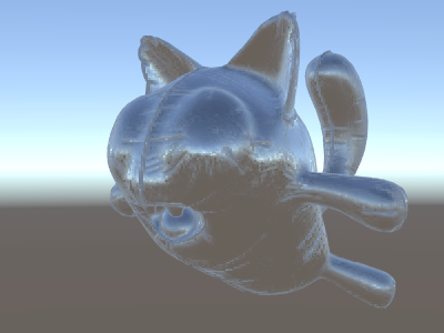
Reflejos del entorno con un Normal Map
A menudo los Normal Maps son utilizados para crear un detalle adicional en objetos, sin crear geometría adicional. Veamos cómo hacer un shader que refleje el entorno, con una textura normal map.
Ahora la matemática se empieza a involucrar mucho, por lo que lo haremos en unos pocos pasos. En el shader de arriba, la dirección del reflejo fue computada por vértice (en el vertex shader), y el fragment shader solamente estaba haciendo la búsqueda del reflection probe cubemap. Sin embargo, una vez empecemos a utilizar normal maps, la normal en sí de la superficie necesita ser calculada en una base por-pixel, lo que significa que también necesitamos computar cómo el entorno es reflejado por pixel!
Entonces primero que todo, volamos a re-escribir el shader de arriba para que haga lo mismo, excepto que nosotros vamos a mover algunos cálculos al fragment shader, para que estén computados por pixel:
Shader "Unlit/SkyReflection Per Pixel"
{
    SubShader
    {
        Pass
        {
            CGPROGRAM
            #pragma vertex vert
            #pragma fragment frag
            #include "UnityCG.cginc"

            struct v2f {
                float3 worldPos : TEXCOORD0;
                half3 worldNormal : TEXCOORD1;
                float4 pos : SV_POSITION;
            };

            v2f vert (float4 vertex : POSITION, float3 normal : NORMAL)
            {
                v2f o;
                o.pos = UnityObjectToClipPos(vertex);
                o.worldPos = mul(_Object2World, vertex).xyz;
                o.worldNormal = UnityObjectToWorldNormal(normal);
                return o;
            }

            fixed4 frag (v2f i) : SV_Target
            {
                // compute view direction and reflection vector
                // per-pixel here
                half3 worldViewDir = normalize(UnityWorldSpaceViewDir(i.worldPos));
                half3 worldRefl = reflect(-worldViewDir, i.worldNormal);

                // same as in previous shader
                half4 skyData = UNITY_SAMPLE_TEXCUBE(unity_SpecCube0, worldRefl);
                half3 skyColor = DecodeHDR (skyData, unity_SpecCube0_HDR);
                fixed4 c = 0;
                c.rgb = skyColor;
                return c;
            }
            ENDCG
        }
    }
}
Esto por si solo no nos da mucho – el shader se ve exactamente igual, excepto que ahora corre más lento ya que hace más cálculos para cada uno de todos los pixeles en la pantalla, en vez de hacerlo para cada uno de los vértices del modelo. No obstante, nosotros vamos a necesitar estos cálculos muy pronto. Una fidelidad mayor de gráficos a menudo necesitan más shaders complejos.
Nosotros tendremos que aprender una nueva cosa ahora también; el tal llamado “tangent space” (espacio tangencial). Las texturas Normal Map a menudo son expresadas en espacio de coordenadas que pueden ser pensadas como “el seguimiento de la superficie” del modelo. En nuestro shader nosotros vamos a necesitar saber los vectores de la base del espacio tangente, leer el vector normal de la textura, transformarlo al espacio del mundo, y luego hacer toda la matemática del shader de arriba. ¡Hagámoslo!
Shader "Unlit/SkyReflection Per Pixel"
{
    Properties {
        // normal map texture on the material,
        // default to dummy "flat surface" normalmap
        _BumpMap("Normal Map", 2D) = "bump" {}
    }
    SubShader
    {
        Pass
        {
            CGPROGRAM
            #pragma vertex vert
            #pragma fragment frag
            #include "UnityCG.cginc"

            struct v2f {
                float3 worldPos : TEXCOORD0;
                // these three vectors will hold a 3x3 rotation matrix
                // that transforms from tangent to world space
                half3 tspace0 : TEXCOORD1; // tangent.x, bitangent.x, normal.x
                half3 tspace1 : TEXCOORD2; // tangent.y, bitangent.y, normal.y
                half3 tspace2 : TEXCOORD3; // tangent.z, bitangent.z, normal.z
                // texture coordinate for the normal map
                float2 uv : TEXCOORD4;
                float4 pos : SV_POSITION;
            };

            // vertex shader now also needs a per-vertex tangent vector.
            // in Unity tangents are 4D vectors, with the .w component used to
            // indicate direction of the bitangent vector.
            // we also need the texture coordinate.
            v2f vert (float4 vertex : POSITION, float3 normal : NORMAL, float4 tangent : TANGENT, float2 uv : TEXCOORD0)
            {
                v2f o;
                o.pos = UnityObjectToClipPos(vertex);
                o.worldPos = mul(_Object2World, vertex).xyz;
                half3 wNormal = UnityObjectToWorldNormal(normal);
                half3 wTangent = UnityObjectToWorldDir(tangent.xyz);
                // compute bitangent from cross product of normal and tangent
                half tangentSign = tangent.w * unity_WorldTransformParams.w;
                half3 wBitangent = cross(wNormal, wTangent) * tangentSign;
                // output the tangent space matrix
                o.tspace0 = half3(wTangent.x, wBitangent.x, wNormal.x);
                o.tspace1 = half3(wTangent.y, wBitangent.y, wNormal.y);
                o.tspace2 = half3(wTangent.z, wBitangent.z, wNormal.z);
                o.uv = uv;
                return o;
            }

            // normal map texture from shader properties
            sampler2D _BumpMap;

            fixed4 frag (v2f i) : SV_Target
            {
                // sample the normal map, and decode from the Unity encoding
                half3 tnormal = UnpackNormal(tex2D(_BumpMap, i.uv));
                // transform normal from tangent to world space
                half3 worldNormal;
                worldNormal.x = dot(i.tspace0, tnormal);
                worldNormal.y = dot(i.tspace1, tnormal);
                worldNormal.z = dot(i.tspace2, tnormal);

                // rest the same as in previous shader
                half3 worldViewDir = normalize(UnityWorldSpaceViewDir(i.worldPos));
                half3 worldRefl = reflect(-worldViewDir, worldNormal);
                half4 skyData = UNITY_SAMPLE_TEXCUBE(unity_SpecCube0, worldRefl);
                half3 skyColor = DecodeHDR (skyData, unity_SpecCube0_HDR);
                fixed4 c = 0;
                c.rgb = skyColor;
                return c;
            }
            ENDCG
        }
    }
}
Phew, eso fue bastante involucrado. Pero mire, reflejos normal mapped!
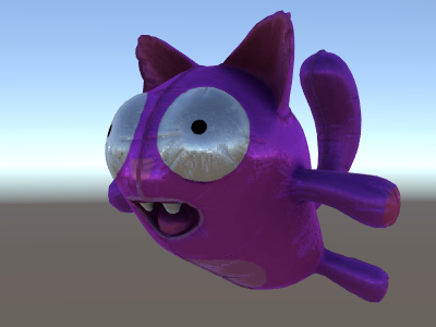
Agregando Más Texturas
Agreguemos más texturas al normal-mapped, cielo que refleja del shader de arriba. Agregaremos el color base de la textura, visto en el primer ejemplo unlit, y un occlusion map para oscurecer las cavidades.
Shader "Unlit/More Textures"
{
    Properties {
        // three textures we'll use in the material
        _MainTex("Base texture", 2D) = "white" {}
        _OcclusionMap("Occlusion", 2D) = "white" {}
        _BumpMap("Normal Map", 2D) = "bump" {}
    }
    SubShader
    {
        Pass
        {
            CGPROGRAM
            #pragma vertex vert
            #pragma fragment frag
            #include "UnityCG.cginc"

            // exactly the same as in previous shader
            struct v2f {
                float3 worldPos : TEXCOORD0;
                half3 tspace0 : TEXCOORD1;
                half3 tspace1 : TEXCOORD2;
                half3 tspace2 : TEXCOORD3;
                float2 uv : TEXCOORD4;
                float4 pos : SV_POSITION;
            };
            v2f vert (float4 vertex : POSITION, float3 normal : NORMAL, float4 tangent : TANGENT, float2 uv : TEXCOORD0)
            {
                v2f o;
                o.pos = UnityObjectToClipPos(vertex);
                o.worldPos = mul(_Object2World, vertex).xyz;
                half3 wNormal = UnityObjectToWorldNormal(normal);
                half3 wTangent = UnityObjectToWorldDir(tangent.xyz);
                half tangentSign = tangent.w * unity_WorldTransformParams.w;
                half3 wBitangent = cross(wNormal, wTangent) * tangentSign;
                o.tspace0 = half3(wTangent.x, wBitangent.x, wNormal.x);
                o.tspace1 = half3(wTangent.y, wBitangent.y, wNormal.y);
                o.tspace2 = half3(wTangent.z, wBitangent.z, wNormal.z);
                o.uv = uv;
                return o;
            }

            // textures from shader properties
            sampler2D _MainTex;
            sampler2D _OcclusionMap;
            sampler2D _BumpMap;

            fixed4 frag (v2f i) : SV_Target
            {
                // same as from previous shader...
                half3 tnormal = UnpackNormal(tex2D(_BumpMap, i.uv));
                half3 worldNormal;
                worldNormal.x = dot(i.tspace0, tnormal);
                worldNormal.y = dot(i.tspace1, tnormal);
                worldNormal.z = dot(i.tspace2, tnormal);
                half3 worldViewDir = normalize(UnityWorldSpaceViewDir(i.worldPos));
                half3 worldRefl = reflect(-worldViewDir, worldNormal);
                half4 skyData = UNITY_SAMPLE_TEXCUBE(unity_SpecCube0, worldRefl);
                half3 skyColor = DecodeHDR (skyData, unity_SpecCube0_HDR);
                fixed4 c = 0;
                c.rgb = skyColor;

                // modulate sky color with the base texture, and the occlusion map
                fixed3 baseColor = tex2D(_MainTex, i.uv).rgb;
                fixed occlusion = tex2D(_OcclusionMap, i.uv).r;
                c.rgb *= baseColor;
                c.rgb *= occlusion;

                return c;
            }
            ENDCG
        }
    }
}
El gato globo se está viendo bien!
Ejemplos Texturing Shader
Patrón de tablero de ajedrez procedimental
Aquí hay un shader que tiene como salida un patrón de un tablero de ajedrez basado en las coordenadas de textura de un mesh:
Shader "Unlit/Checkerboard"
{
    Properties
    {
        _Density ("Density", Range(2,50)) = 30
    }
    SubShader
    {
        Pass
        {
            CGPROGRAM
            #pragma vertex vert
            #pragma fragment frag
            #include "UnityCG.cginc"

            struct v2f
            {
                float2 uv : TEXCOORD0;
                float4 vertex : SV_POSITION;
            };

            float _Density;

            v2f vert (float4 pos : POSITION, float2 uv : TEXCOORD0)
            {
                v2f o;
                o.vertex = UnityObjectToClipPos(pos);
                o.uv = uv * _Density;
                return o;
            }

            fixed4 frag (v2f i) : SV_Target
            {
                float2 c = i.uv;
                c = floor(c) / 2;
                float checker = frac(c.x + c.y) * 2;
                return checker;
            }
            ENDCG
        }
    }
}
El deslizador de densidad en el bloque Properties controla qué tan denso el tablero de ajedrez es. En el vertex shader, las UVs del mesh son multiplicadas por el valor de densidad para llevarlas de un rango de 0 a 1 a un rango de 0 a densidad. Digamos que la densidad fue configurada a 30 - esto hará que el input i.uv del fragment shader contenga valores de punto flotante desde cero a 30 para varios lugares de dónde el mesh se renderiza.
Luego el código fragment shader solo toma la parte del integer de la coordenada input utilizando la función integrada floor de HLSL, y lo divide por dos. Recuerde que las coordenadas input eran números de 0 a 30; esto las hace ser “cuantificados” a valores de 0, 0.5, 1, 1.5, 2, 2.5, y así. Esto fue hecho en ambos los componentes x y y de la coordenada input.
Luego, nosotros vamos a agregar estas coordenadas X y Y juntas (cada una teniendo uno valores posibles de 0, 0,5, 1, 1.5, …) y solamente tomar la parte fraccional utilizando otra función HLSL integrada, frac. El resultado de esto puede ser ya sea 0.0 o 0.5. Nosotros luego lo multiplicamos por dos para sea 0.0 o 1.0, y el output como un color (esto resulta en un color negro o blanco respectivamente).
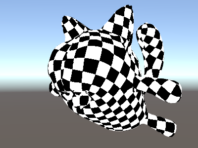
Texturización Tri-planar
Para meshes complejos o procedural, en vez de texturizarlos utilizando las coordenadas regulares UV, a veces es más útil simplemente “proyectar” la textura al objeto desde tres direcciones principales. Esto se llama “tri-planar” texturing. La idea es utilizar surface normal para pesar las tres direcciones de textura. Aquí está el shader:
Shader "Unlit/Triplanar"
{
    Properties
    {
        _MainTex ("Texture", 2D) = "white" {}
        _Tiling ("Tiling", Float) = 1.0
        _OcclusionMap("Occlusion", 2D) = "white" {}
    }
    SubShader
    {
        Pass
        {
            CGPROGRAM
            #pragma vertex vert
            #pragma fragment frag
            #include "UnityCG.cginc"

            struct v2f
            {
                half3 objNormal : TEXCOORD0;
                float3 coords : TEXCOORD1;
                float2 uv : TEXCOORD2;
                float4 pos : SV_POSITION;
            };

            float _Tiling;

            v2f vert (float4 pos : POSITION, float3 normal : NORMAL, float2 uv : TEXCOORD0)
            {
                v2f o;
                o.pos = UnityObjectToClipPos(pos);
                o.coords = pos.xyz * _Tiling;
                o.objNormal = normal;
                o.uv = uv;
                return o;
            }

            sampler2D _MainTex;
            sampler2D _OcclusionMap;

            fixed4 frag (v2f i) : SV_Target
            {
                // use absolute value of normal as texture weights
                half3 blend = abs(i.objNormal);
                // make sure the weights sum up to 1 (divide by sum of x+y+z)
                blend /= dot(blend,1.0);
                // read the three texture projections, for x,y,z axes
                fixed4 cx = tex2D(_MainTex, i.coords.yz);
                fixed4 cy = tex2D(_MainTex, i.coords.xz);
                fixed4 cz = tex2D(_MainTex, i.coords.xy);
                // blend the textures based on weights
                fixed4 c = cx * blend.x + cy * blend.y + cz * blend.z;
                // modulate by regular occlusion map
                c *= tex2D(_OcclusionMap, i.uv);
                return c;
            }
            ENDCG
        }
    }
}

Calculando la iluminación
Típicamente cuando usted quiere un shader que funcione con el pipeline de iluminación de Unity, usted escribiría un surface shader. Esto hace la mayoría del “trabajo pesado” para usted, y su código shader solamente necesita definir propiedades de la superficie.
No obstante, en algunos casos usted quiere bypass (evitar) el camino del standard surface shader; ya sea porque usted quiere solamente soportar algún sub-conjunto limitado del pipeline de iluminación entero por razones de rendimiento, o usted quiere simplemente hacer cosas personalizadas que no son “standard lighting” (de iluminación estándar). Los siguientes ejemplos le mostrarán como obtener los datos de iluminación de vertex y fragment shader escritos manualmente. Mirando al código generado de los surface shaders (vía shader inspector) es también un buen recursos de aprendizaje.
Simple Diffuse Lighting (Iluminación difusa simple)
La primera cosa que nosotros necesitamos hacer es indicar que nuestro shader en realidad necesita información de iluminación pasada a él. El rendering pipeline de Unity soporta varias maneras de renderizar, aquí nosotros estaremos utilizando el predeterminado forward rendering.
Comenzaremos al soportar solo una directional light. Forward Rendering en Unity funciona al renderizar la directional light, ambient, lightmaps y reflections principales en un solo pass llamado ForwardBase. En el shader, esto es indicado al agregar un pass tag: Tags {"LightMode"="ForwardBase"}. Esto hará que los datos de la directional light sean passed al shader vía algunas de las variables integradas.
Aquí está el shader que computa un simple diffuse lighting por vértice, y utiliza una sola textura principal:
Shader "Lit/Simple Diffuse"
{
    Properties
    {
        [NoScaleOffset] _MainTex ("Texture", 2D) = "white" {}
    }
    SubShader
    {
        Pass
        {
            // indicate that our pass is the "base" pass in forward
            // rendering pipeline. It gets ambient and main directional
            // light data set up; light direction in _WorldSpaceLightPos0
            // and color in _LightColor0
            Tags {"LightMode"="ForwardBase"}

            CGPROGRAM
            #pragma vertex vert
            #pragma fragment frag
            #include "UnityCG.cginc" // for UnityObjectToWorldNormal
            #include "UnityLightingCommon.cginc" // for _LightColor0

            struct v2f
            {
                float2 uv : TEXCOORD0;
                fixed4 diff : COLOR0; // diffuse lighting color
                float4 vertex : SV_POSITION;
            };

            v2f vert (appdata_base v)
            {
                v2f o;
                o.vertex = UnityObjectToClipPos(v.vertex);
                o.uv = v.texcoord;
                // get vertex normal in world space
                half3 worldNormal = UnityObjectToWorldNormal(v.normal);
                // dot product between normal and light direction for
                // standard diffuse (Lambert) lighting
                half nl = max(0, dot(worldNormal, _WorldSpaceLightPos0.xyz));
                // factor in the light color
                o.diff = nl * _LightColor0;
                return o;
            }

            sampler2D _MainTex;

            fixed4 frag (v2f i) : SV_Target
            {
                // sample texture
                fixed4 col = tex2D(_MainTex, i.uv);
                // multiply by lighting
                col *= i.diff;
                return col;
            }
            ENDCG
        }
    }
}
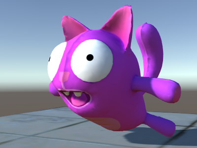
Esto hace que el objeto reaccione a la dirección de la luz- partes de este que encaran la luz son iluminados, y partes que no encaran hacia la luz no son iluminados en absoluto.

Diffuse Lighting con Ambient
El ejemplo de arriba no toma en cuenta el ambient lighting o light probes. Arreglemos esto!
Resulta ser que nosotros podemos hacer esto al agregar una sola linea de código. Ambos datos ambient y light probe son pasados a los shaders en una forma de Spherical Harmonics (armónicos esféricos) y la función ShadeSH9 del archivo include UnityCG.cginc hace todo el trabajo de evaluarlo, dada una normal del espacio del mundo.
Shader "Lit/Diffuse With Ambient"
{
    Properties
    {
        [NoScaleOffset] _MainTex ("Texture", 2D) = "white" {}
    }
    SubShader
    {
        Pass
        {
            Tags {"LightMode"="ForwardBase"}

            CGPROGRAM
            #pragma vertex vert
            #pragma fragment frag
            #include "UnityCG.cginc"
            #include "UnityLightingCommon.cginc"

            struct v2f
            {
                float2 uv : TEXCOORD0;
                fixed4 diff : COLOR0;
                float4 vertex : SV_POSITION;
            };

            v2f vert (appdata_base v)
            {
                v2f o;
                o.vertex = UnityObjectToClipPos(v.vertex);
                o.uv = v.texcoord;
                half3 worldNormal = UnityObjectToWorldNormal(v.normal);
                half nl = max(0, dot(worldNormal, _WorldSpaceLightPos0.xyz));
                o.diff = nl * _LightColor0;

                // the only difference from previous shader:
                // in addition to the diffuse lighting from the main light,
                // add illumination from ambient or light probes
                // ShadeSH9 function from UnityCG.cginc evaluates it,
                // using world space normal
                o.diff.rgb += ShadeSH9(half4(worldNormal,1));
                return o;
            }

            sampler2D _MainTex;

            fixed4 frag (v2f i) : SV_Target
            {
                fixed4 col = tex2D(_MainTex, i.uv);
                col *= i.diff;
                return col;
            }
            ENDCG
        }
    }
}
Este shader de hecho comienza a verse muy similar al Legacy Diffuse shader integrado!
Implementando Shadow Casting (Emisión de Sombras)
Nuestro shader actualmente no puede recibir ni emitir sombras. Implementemos la emisión de sombras primero.
Con el fin de emitir sombras, un shader tiene que tener un ShadowCaster pass type en cualquiera de sus subshaders o en cualquier fallback. El pase ShadowCaster es utilizado para renderizar el objeto al shadowmap, y típicamente es bastante simple . el vertex shader solamente necesita evaluar la posición del vértice, y el fragment shader hace nada. El shadowmap es solamente el buffer, por lo que incluso el output del color por el fragment shader no importa.
Esto significa que para la mayoría de shaders, el shadow caster pass (pase de emisión de sombras) será exactamente el mismo (al menos de que el objeto tenga deformaciones basadas en vertex shader personalizados, o tienen partes alpha cutout / semitransparente). La manera más fácil para traerlo es vía su comando shader UsePass:
Pass
{
    // regular lighting pass
}
// pull in shadow caster from VertexLit built-in shader
UsePass "Legacy Shaders/VertexLit/SHADOWCASTER"
Sin embargo nosotros estamos aprendiendo acá, entonces hagamos lo mismo pero “a mano”. Para un código más corto, nosotros remplazamos el lighting pass (“ForwardBase”) con código que solamente hace ambient sin texturas. Debajo de este hay un “ShadowCaster” pass que hace que el objeto soporte shadow casting (emisión de sombras).
Shader "Lit/Shadow Casting"
{
    SubShader
    {
        // very simple lighting pass, that only does non-textured ambient
        Pass
        {
            Tags {"LightMode"="ForwardBase"}
            CGPROGRAM
            #pragma vertex vert
            #pragma fragment frag
            #include "UnityCG.cginc"
            struct v2f
            {
                fixed4 diff : COLOR0;
                float4 vertex : SV_POSITION;
            };
            v2f vert (appdata_base v)
            {
                v2f o;
                o.vertex = UnityObjectToClipPos(v.vertex);
                half3 worldNormal = UnityObjectToWorldNormal(v.normal);
                // only evaluate ambient
                o.diff.rgb = ShadeSH9(half4(worldNormal,1));
                o.diff.a = 1;
                return o;
            }
            fixed4 frag (v2f i) : SV_Target
            {
                return i.diff;
            }
            ENDCG
        }

        // shadow caster rendering pass, implemented manually
        // using macros from UnityCG.cginc
        Pass
        {
            Tags {"LightMode"="ShadowCaster"}

            CGPROGRAM
            #pragma vertex vert
            #pragma fragment frag
            #pragma multi_compile_shadowcaster
            #include "UnityCG.cginc"

            struct v2f {
                V2F_SHADOW_CASTER;
            };

            v2f vert(appdata_base v)
            {
                v2f o;
                TRANSFER_SHADOW_CASTER_NORMALOFFSET(o)
                return o;
            }

            float4 frag(v2f i) : SV_Target
            {
                SHADOW_CASTER_FRAGMENT(i)
            }
            ENDCG
        }
    }
}
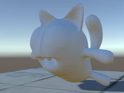
Ahora hay un plano debajo de este, que utiliza un Diffuse shader regular integrado, para que podamos ver que nuestras sombras funcionan (recuerde, nuestro actual shader no soporta recibir sombras todavía!).
Nosotros hemos utilizado la directiva #pragma multi_compile_shadowcaster. Esto causa que el shader sea compilado a varias variantes con diferentes macros pre-processesor definidas para cada (ver
la página múltiples variantes shader para detalles). Cuando renderice al shadowmap, los casos de point lights vs otro tipo de luces necesitan una pequeña diferencia en shader code, y es por esto que esta directiva se necesita.
Recibiendo Sombras
Implementar el soporte para recibir sombras va a requerir compilar el lighting pass base a
varias variantes, para manejar casos de “directional light sin sombras” y “directional light con sombras” adecuadamente. La directiva #pragma multi_compile_fwdbase hace esto (Ver
múltiples variantes shader para detalles). De hecho, hace mucho más:
también compila variantes para los diferentes tipos de lightmaps, realtime GI estando prendido o apagado etc. Actualmente nosotros no necesitamos todo esto, entonces omitiremos esas variantes.
Luego para obtener las computaciones de las sombras actuales, nosotros vamos a #include "AutoLight.cginc" shader Includes integrados y utilizar las macros SHADOW_COORDS, TRANSFER_SHADOW, SHADOW_ATTENUATION de esta.
Aquí está el shader:
Shader "Lit/Diffuse With Shadows"
{
    Properties
    {
        [NoScaleOffset] _MainTex ("Texture", 2D) = "white" {}
    }
    SubShader
    {
        Pass
        {
            Tags {"LightMode"="ForwardBase"}
            CGPROGRAM
            #pragma vertex vert
            #pragma fragment frag
            #include "UnityCG.cginc"
            #include "Lighting.cginc"

            // compile shader into multiple variants, with and without shadows
            // (we don't care about any lightmaps yet, so skip these variants)
            #pragma multi_compile_fwdbase nolightmap nodirlightmap nodynlightmap novertexlight
            // shadow helper functions and macros
            #include "AutoLight.cginc"

            struct v2f
            {
                float2 uv : TEXCOORD0;
                SHADOW_COORDS(1) // put shadows data into TEXCOORD1
                fixed3 diff : COLOR0;
                fixed3 ambient : COLOR1;
                float4 pos : SV_POSITION;
            };
            v2f vert (appdata_base v)
            {
                v2f o;
                o.pos = UnityObjectToClipPos(v.vertex);
                o.uv = v.texcoord;
                half3 worldNormal = UnityObjectToWorldNormal(v.normal);
                half nl = max(0, dot(worldNormal, _WorldSpaceLightPos0.xyz));
                o.diff = nl * _LightColor0.rgb;
                o.ambient = ShadeSH9(half4(worldNormal,1));
                // compute shadows data
                TRANSFER_SHADOW(o)
                return o;
            }

            sampler2D _MainTex;

            fixed4 frag (v2f i) : SV_Target
            {
                fixed4 col = tex2D(_MainTex, i.uv);
                // compute shadow attenuation (1.0 = fully lit, 0.0 = fully shadowed)
                fixed shadow = SHADOW_ATTENUATION(i);
                // darken light's illumination with shadow, keep ambient intact
                fixed3 lighting = i.diff * shadow + i.ambient;
                col.rgb *= lighting;
                return col;
            }
            ENDCG
        }

        // shadow casting support
        UsePass "Legacy Shaders/VertexLit/SHADOWCASTER"
    }
}
Mire, nosotros tenemos ya sombras!
Otros ejemplos Shader
Niebla
Shader "Custom/TextureCoordinates/Fog" {
    SubShader {
        Pass {
            CGPROGRAM
            #pragma vertex vert
            #pragma fragment frag

            //Needed for fog variation to be compiled.
            #pragma multi_compile_fog

            #include "UnityCG.cginc"

            struct vertexInput {
                float4 vertex : POSITION;
                float4 texcoord0 : TEXCOORD0;
            };

            struct fragmentInput{
                float4 position : SV_POSITION;
                float4 texcoord0 : TEXCOORD0;

                //Used to pass fog amount around number should be a free texcoord.
                UNITY_FOG_COORDS(1)
            };

            fragmentInput vert(vertexInput i){
                fragmentInput o;
                o.position = UnityObjectToClipPos(i.vertex);
                o.texcoord0 = i.texcoord0;

                //Compute fog amount from clip space position.
                UNITY_TRANSFER_FOG(o,o.position);
                return o;
            }

            fixed4 frag(fragmentInput i) : SV_Target {
                fixed4 color = fixed4(i.texcoord0.xy,0,0);

                //Apply fog (additive pass are automatically handled)
                UNITY_APPLY_FOG(i.fogCoord, color);

                //to handle custom fog color another option would have been
                //#ifdef UNITY_PASS_FORWARDADD
                //  UNITY_APPLY_FOG_COLOR(i.fogCoord, color, float4(0,0,0,0));
                //#else
                //  fixed4 myCustomColor = fixed4(0,0,1,0);
                //  UNITY_APPLY_FOG_COLOR(i.fogCoord, color, myCustomColor);
                //#endif

                return color;
            }
            ENDCG
        }
    }
}
Usted puede descargar los ejemplos mostrados arriba como un proyecto Unity zipped.
Lecturas adicionales
Copyright © 2023 Unity Technologies
优美缔软件(上海)有限公司 版权所有
"Unity"、Unity 徽标及其他 Unity 商标是 Unity Technologies 或其附属机构在美国及其他地区的商标或注册商标。其他名称或品牌是其各自所有者的商标。
公安部备案号:
31010902002961